Method of fabrication of drip irrigation conduits

A technology of drip irrigation pipes and injectors, which is applied in the field of production of drip irrigation pipes or pipes, can solve the problems of bulky, expensive, and complicated equipment, achieve the effect of omitting detection and punching devices, and increase the production speed of pipes

Inactive Publication Date: 2005-07-20
托马斯机械股份有限公司
View PDF2 Cites 7 Cited by
  • Summary
  • Abstract
  • Description
  • Claims
  • Application Information

AI Technical Summary

Problems solved by technology

This equipment is bulky, complex and relatively expensive, which significantly increases the cost of such equipment
Incident

Method used


Image

  • Method of fabrication of drip irrigation conduits
  • Method of fabrication of drip irrigation conduits
  • Method of fabrication of drip irrigation conduits

Examples


Embodiment Construction

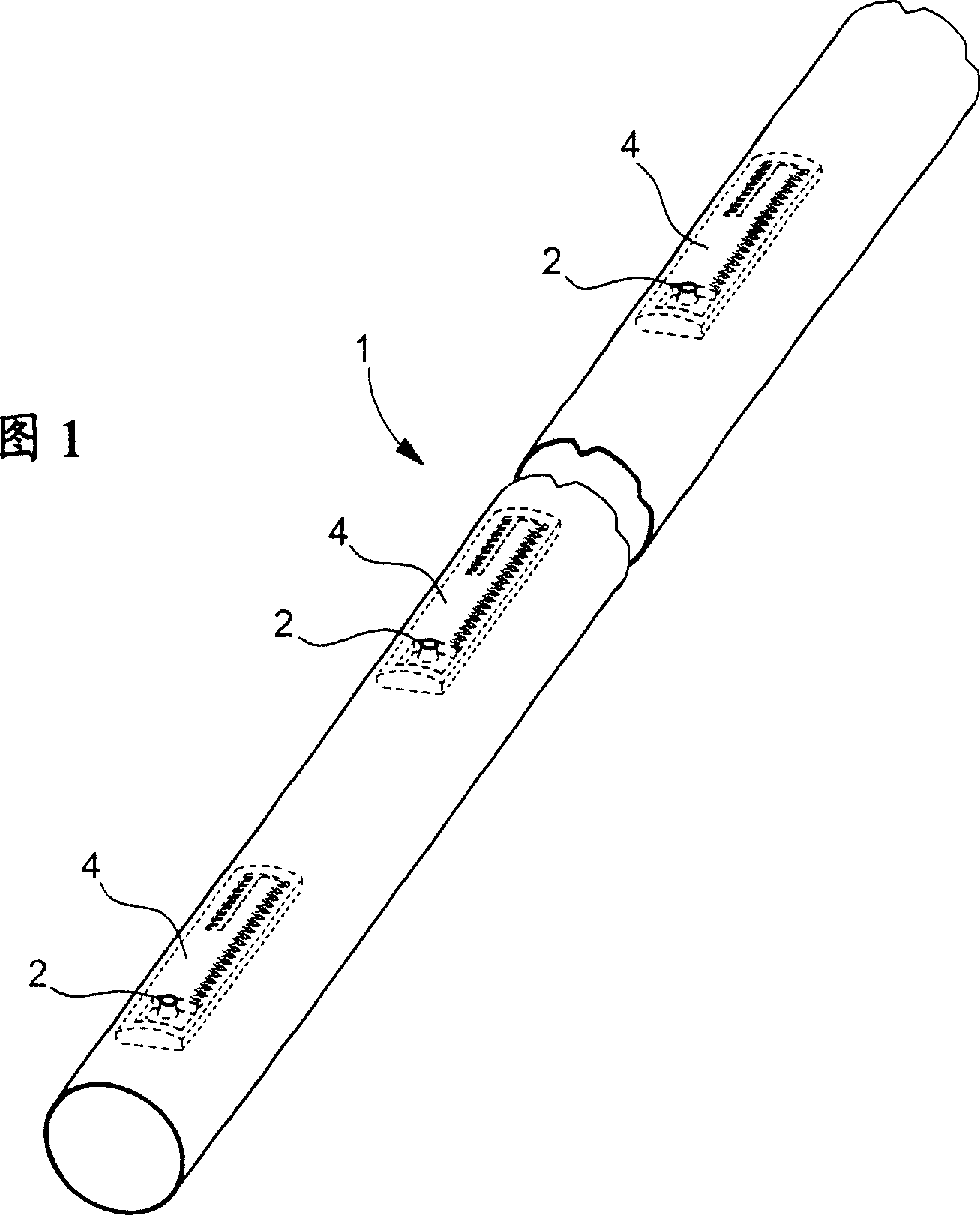
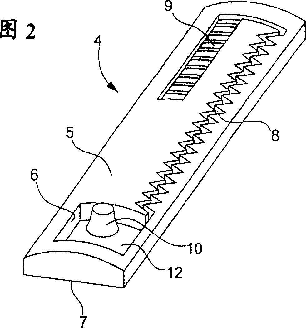
[0035] Figure 1 shows a water supply pipe or pipe 1 made of plastic such as polyethylene having drainage holes or outlets 2 spaced at regular intervals through which water can flow or trickle to aquatic plants (not shown). out). In the vicinity of the hole 2 there is provided an injector 4 placed inside the tube and thus not visible from the outside, the structure of which is explained with reference to FIG. 2 .

[0036] The injector is a part made of plastic, ideally of the same composition as the pipe 1, although this is not necessary. The injector 4 generally has a body in the shape of an elongated parallelepiped with an “outer” surface 5 whose cross-section has a curvilinear shape corresponding to the curvature of the inner wall of the tube 1 . In the surface 5, a water collection chamber 6 is cut out near the center of substantially one end of the example shown, not reaching the opposite face 7 of the injector. As clearly shown in FIG. 2 , there is provided in the surfa...


PUM


Abstract

The droplet former (4), designed to be located at intervals to the inside of an irrigation pipe to control the flow of water through its outlets, consists of a plastic bar (5) with a water collection chamber (10) fed by a passage (9) and a labyrinth channel (8). The bar is attached to the inner surface of the irigation pipe, especially by welding, so that the collection chamber is aligned with a pipe outlet. The collection chamber has a central projection that lifts the wall of the irrigation pipe from the inside so that it can be trimmed to make an outlet with its edges in contact with the projection to form a valve. - An INDEPENDENT CLAIM is included for a method of manufacturing a water droplet former.

Description

technical field [0001] The present invention relates to a method of producing drip irrigation pipes or pipes. Background technique [0002] For some irrigation, the use of so-called "drip pipes" is a common technique. This is a pipe whose wall is perforated with small-sized holes at predetermined intervals, and water flows into the ground through these small-sized holes. In order to precisely control the flow from the orifice, there is provided a flow rate limiter, usually called an "emitter", consisting of a plastic part, which is glued to the inner wall of the tube. On the side facing the inner wall of the tube, the part has a hollow forming a water collection chamber. The water collecting chamber is connected to the inner space of the pipe through a passage having a predetermined pressure loss such as a labyrinth passage. The labyrinth is formed by a prefabricated groove on the surface of the injector facing the inner surface of the tube. [0003] In fact, in most cas...

Claims


Application Information

Patent Timeline
IPC IPC(8): A01G25/02B29C48/09B29C48/10B29C48/157B29C48/355B29C48/90B29C69/02
CPCA01G25/026B29C47/028B29C47/0057B29C47/34B29C47/0038B29C47/0023B29C47/901A01G25/023B29C48/09B29C48/10B29C48/001B29C48/0018B29C48/157B29C48/355B29C48/9155B29C48/919B29C48/901Y02A40/22
Inventor T·贝尔瑙尔E·克切尔
Owner 托马斯机械股份有限公司
Why Eureka
Try Eureka