Back-light mechanism for liquid crystal display device

A liquid crystal display device and light source technology, which is applied to lighting devices, optics, light sources, etc., can solve the problems of increased manufacturing cost, increased number of parts, complicated structure, etc. Effect

Inactive Publication Date: 2005-07-20
YAMAMOTO PLASTIC IND
View PDF2 Cites 1 Cited by
  • Summary
  • Abstract
  • Description
  • Claims
  • Application Information

AI Technical Summary

Problems solved by technology

However, in a large liquid crystal display device, in order not to cause insufficient and uneven illumination, a plurality of linear light sources must

Method used


Image

  • Back-light mechanism for liquid crystal display device
  • Back-light mechanism for liquid crystal display device
  • Back-light mechanism for liquid crystal display device

Examples


Embodiment Construction

[0030] Next, embodiments of a backlight mechanism for a liquid crystal display device according to the present invention will be described with reference to the drawings.

[0031] figure 1 ~ FIG. 6 shows an embodiment of the backlight mechanism for the liquid crystal display device of the present invention.

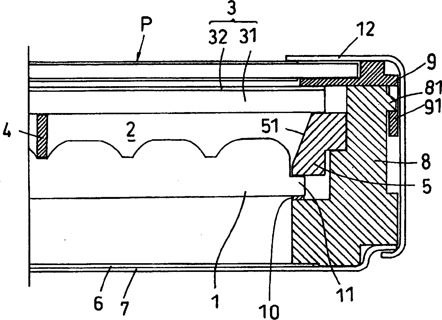
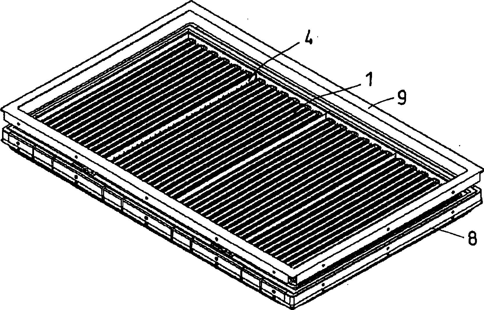
[0032] The backlight mechanism for this liquid crystal display device adopts a planar light source as a light source, specifically, adopts a surface-emitting flat lamp 1 made of a fluorescent tube as shown in FIG. The air layer 2 is formed between them, and the light diffusion member 3 is supported by the back side of the support member 4 .

[0033] In addition, depending on the shape of the backlight mechanism for liquid crystal display devices, one surface emitting flat lamp 1 may be used, or an appropriate number of flat lamps 1 may be used in combination.

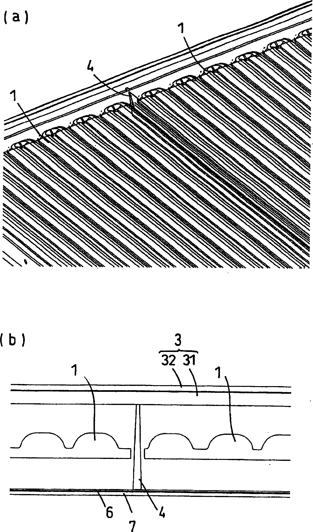
[0034] At this time, if figure 1 As shown, the support member 4 can be arranged on the surface of the surfa...


PUM


Abstract

To provide a backlight unit for a liquid crystal display device in which the lack or unevenness of illumination does not occur even in the case of a large-sized liquid crystal display device, and which prevents a light diffusion member by the own weight of the light diffusion member or a heat generated from a surface emitting flat lamp, can illuminate in a high quality level, has the small number of components, and can reduce a manufacturing cost without requiring a time and effort in manufacturing by a simple structure. the surface emitting flat lamp 1 used as a light source, and an air layer 2 formed between the flat lamp 1 and the light diffusion member 3. The light diffusion member 3 is supported by a supporting member 4 from the back surface side.

Description

technical field [0001] The invention relates to a backlight mechanism for a liquid crystal display device, in particular to a backlight mechanism for a liquid crystal display device in which a surface-emitting flat lamp is used as a light source. Background technique [0002] In recent years, liquid crystal display devices equipped with backlight mechanisms have been used as thin display devices for televisions and computers. [0003] The backlight mechanism used in such liquid crystal display devices in the past mostly adopts the edge light mode. That is, if Figure 7 ~ Figure 8 As shown, a linear light source 104 such as a fluorescent tube is arranged at the end of a light-transmitting light guide plate 101 (see Patent Document 1). [0004] This edge light method is usually on the back side of the light guide plate 101, partially covered with a light diffusing material 106 having a larger refractive index than the material of the light guide plate 101, and almost covering...

Claims


Application Information

Patent Timeline
IPC IPC(8): G02F1/13357F21S2/00F21Y105/00G02F1/133G02F1/1335
CPCG02B5/0278G02F1/133604G02F1/133606G02F1/133567
Inventor 山本胜实
Owner YAMAMOTO PLASTIC IND
Why Eureka
Try Eureka