DC inverting electronic ballast

A technology of electronic ballast and electronic switch, which is applied to the use of electric light sources, electrical components, and gas discharge lamps. cost reduction effect

Inactive Publication Date: 2005-07-27
李卫阳
View PDF0 Cites 1 Cited by
  • Summary
  • Abstract
  • Description
  • Claims
  • Application Information

AI Technical Summary

Problems solved by technology

[0002] In the prior art, there are high-frequency ballasts and DC ballasts. Although high-frequency ballasts have the characteristics of energy saving and no flicker, their cost is high, and the high-frequency radiated electromagnetic waves produced have harmful effects on radio receiving equipment. influence, harm to the human body
Although the DC ballast solves the problem of no flicker and no radiation, this technology requires the use of a special DC lamp, which will cause electrophoresis when used for a long time, making one end of the lamp brighter and the other end darker, and the DC The cost of special lamps is relatively high, which is difficult to be accepted by the majority of users

Method used


Image

  • DC inverting electronic ballast
  • DC inverting electronic ballast
  • DC inverting electronic ballast

Examples


Embodiment Construction

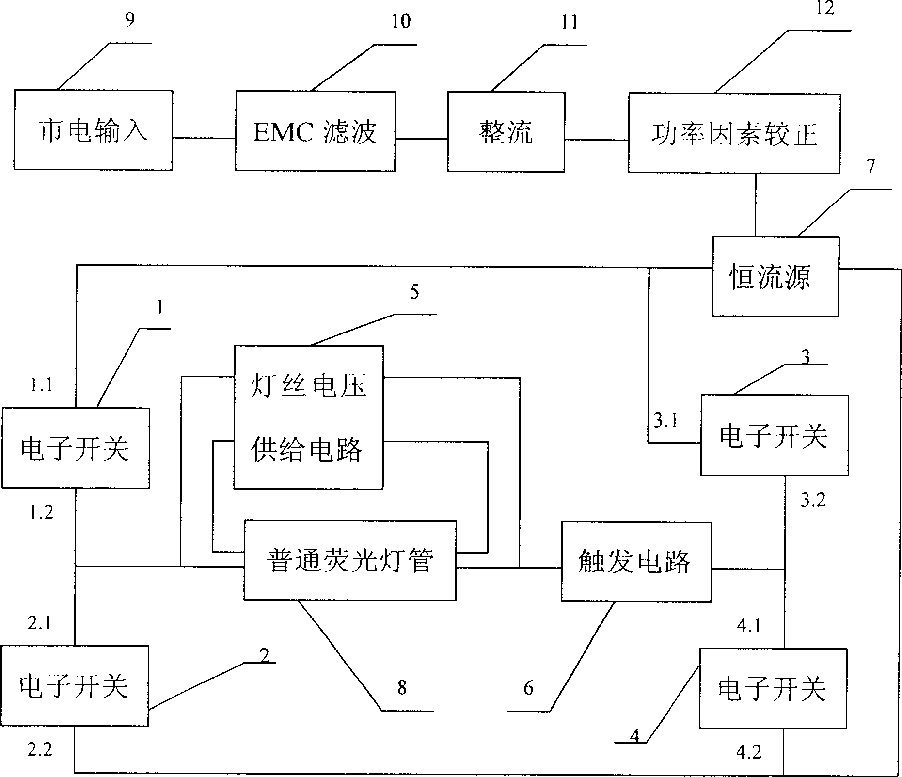
[0016] according to Figure 1 to Figure 6 In the embodiment of the present invention with the above-mentioned structure shown in the DC reverse electronic ballast, 9 strings of mains input are electrically connected to the EMC filter circuit 10, the rectifier circuit 11 and the power factor correction circuit 12 in turn to form a constant current source 7. The common The filaments at both ends of the fluorescent tube 8 are connected in series with a filament voltage supply circuit 5, the right end of the ordinary fluorescent tube 8 is respectively connected to the terminal 3.2 of the electronic switch 3 and the terminal 4.1 of the electronic switch 4 through the trigger circuit 6, and the left end of the ordinary fluorescent tube 8 is respectively connected to the terminal of the electronic switch 1 Terminal 1.2 and terminal 2.1 of the electronic switch 2, terminal 1.1 of the above-mentioned electronic switch 1 and terminal 3.1 of the electronic switch 3 are all electrically co...


PUM


Abstract

The invention contains mains power input and fluorescent tube. The mains power input is connected in series with EMC filter circuit, rectifying circuit and FPC circuit to form constant current source. The filament of both ends of fluorescent tube is connected in series with filament voltage supplying circuit. The right end of fluorescent tube is connected with 3,2 end of electronic switch 3 and 4, 1 end of electronic switch 4 through triggering circuit. The left end of fluorescent tube is connected 1.2 end of electronic switch 1 and 2.1 end of the electronic switch 2. The 1.1 end of the electronic switch 1 and 3.1 end of electronic switch 3 is connected with the one end of constant current source. 2.2 end of electronic switch 2 and 4.2 end of electronic switch 4 is connected with another end of constant current source.

Description

technical field [0001] The invention relates to a fluorescent tube ballast. Background technique [0002] In the prior art, there are high-frequency ballasts and DC ballasts. Although high-frequency ballasts have the characteristics of energy saving and no flicker, their cost is high, and the high-frequency radiated electromagnetic waves produced have harmful effects on radio receiving equipment. Influence, there is harm to the human body. Although the DC ballast solves the problem of no flicker and no radiation, this technology requires the use of a special DC lamp, which will cause electrophoresis when used for a long time, making one end of the lamp brighter and the other end darker, and the DC The cost of special-purpose lamp tube is relatively high, and it is difficult to be accepted by the majority of users. Contents of the invention [0003] The invention adopts a new method, can achieve no flicker and no radiation, and can use common lamp tubes. That is, DC reve...

Claims


Application Information

Patent Timeline
Patent Type & Authority Applications(China)
IPC IPC(8): H05B41/282
CPCY02B20/183Y02B20/00
Inventor 李卫阳彭五一
Owner 李卫阳
Why Eureka
Try Eureka