Cathode ray tube-use glass panel and inspection method therefore and inspection device therefor

A cathode ray tube and glass panel technology, which is applied to cathode ray/electron beam tube shells/containers, measuring devices, screen tubes, etc., can solve the problems of improper disposal of vacuum tubes and three-dimensional complexity.

Inactive Publication Date: 2005-07-27
NIPPON ELECTRIC GLASS CO LTD
View PDF0 Cites 7 Cited by
  • Summary
  • Abstract
  • Description
  • Claims
  • Application Information

AI Technical Summary

Problems solved by technology

[0017] The object of the present invention is not only the presence of defects on the surface parallel to the inner and outer surfaces of the screen part of the panel, but also the presence of defects in the thickness direction of the screen part can be accurately and easily detected, avoiding the Complicated defect countermeasures and inappropriate disposal of vacuum tubes due to the inability to know the existence of three-dimensional internal defects

Method used


Image

  • Cathode ray tube-use glass panel and inspection method therefore and inspection device therefor
  • Cathode ray tube-use glass panel and inspection method therefore and inspection device therefor
  • Cathode ray tube-use glass panel and inspection method therefore and inspection device therefor

Examples


Embodiment Construction

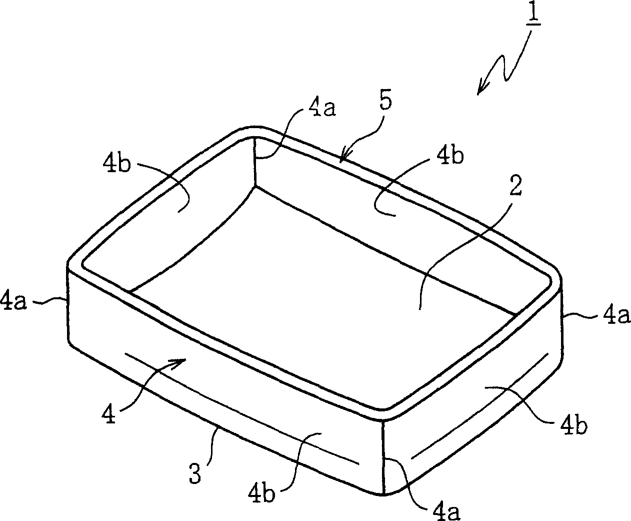
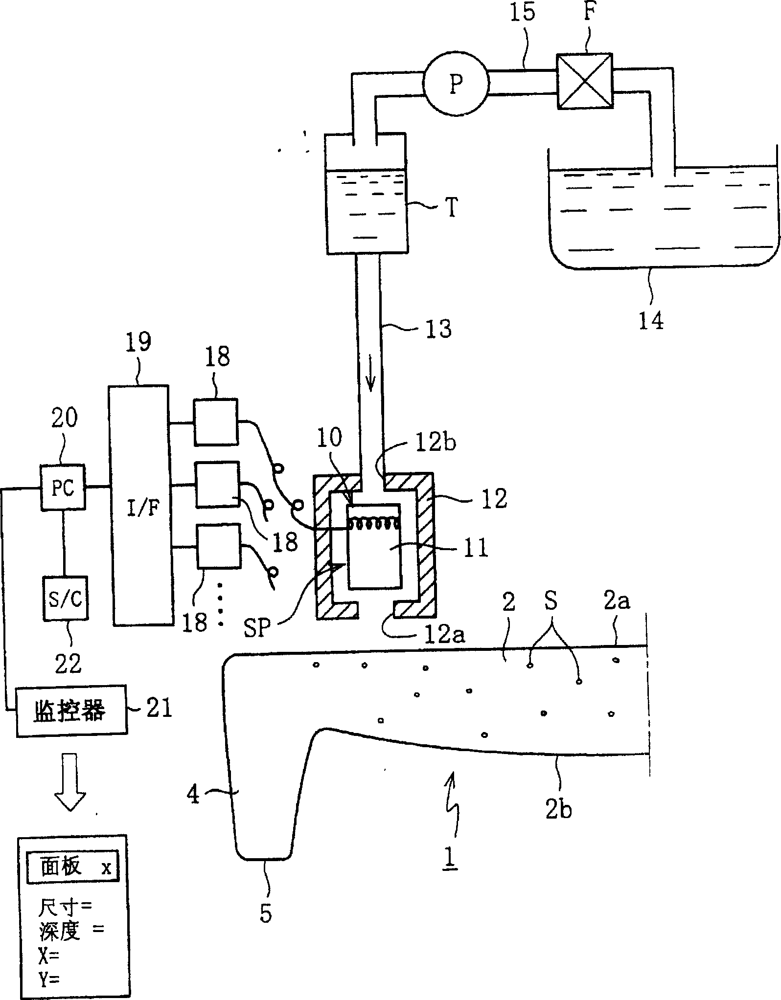
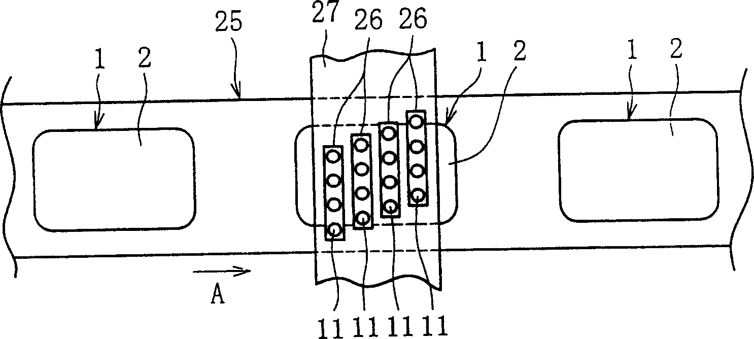
[0073] Hereinafter, description will be given based on drawings of embodiments of the present invention. figure 1 Shown is a perspective view of a glass panel for a projection type cathode ray tube (hereinafter simply referred to as a panel) according to an embodiment of the present invention. figure 2 Shown is a schematic front view of the main part of the detection device of the panel. FIG. 3(a) is a schematic plan view of the entire detection device. Fig. 3(b) is a schematic front view of the entire detection device.

[0074] Such as figure 1As shown, the panel 1 is provided with: a screen portion 2 that is equipped with an effective image display; an edge portion that is connected at a substantially right angle around the screen portion 2 by a mixed R portion 3 around the screen portion 2 4. Also, the edge portion 4 has each side portion 4b connected by four diagonal portions 4a, and an end face 5 sealed at the joint of the funnel is formed at the opening of the front...


PUM

PropertyMeasurementUnit
lengthaaaaaaaaaa
diameteraaaaaaaaaa

Abstract

The sizes and the depths of inner defects (S) in the face portion (2) of a panel (1) are detected by ultrasonic wave. Preferably, ultrasonic wave is oscillated from the outer surface (2a) side of the face portion (2) toward the inner surface (2b) side, and a reflection wave reflected off the inner surface (2b) side is received to thereby detect the sizes of inner defects (S) and the distances from the inner surface (2a) of the inner defects (S). Propagation of ultrasonic wave external to the face portion (2) when ultrasonic wave is oscillated and received is carried out with a non-compressive fluid as a medium.

Description

technical field [0001] The present invention relates to a glass panel for a cathode ray tube, an inspection method and an inspection device thereof, and particularly relates to a technique for detecting internal defects existing in a screen portion of a glass panel for a cathode ray tube. Background technique [0002] Generally, a so-called direct view type cathode ray tube and a projection type cathode ray tube are known as cathode ray tubes which are components of television receivers and the like. Such a cathode ray tube has a panel having a roughly rectangular screen portion on which an image can be projected, and a funnel having a small roughly circular opening starting from a large rectangular opening. The roughly funnel-shaped sidewall portion. A neck portion into which an electron gun is inserted is connected to the small opening of the funnel. Furthermore, the panels and funnels are made by pressing molten glass using a mold consisting of a female and a male form....

Claims


Application Information

Patent Timeline
Patent Type & Authority Applications(China)
IPC IPC(8): G01B17/00G01N29/07G01N29/28H01J9/42H01J29/86
CPCG01N29/28G01N2291/2698G01N2291/0232G01N2291/044G01N29/07Y10T428/131H01J9/42
Inventor 秋山茂彦桐畑义夫三国隆司洼坂卫
Owner NIPPON ELECTRIC GLASS CO LTD
Why Eureka
Try Eureka