Engine foot starting structure

A technology of engine and starting rod, which is applied in the direction of engine starting, engine components, machines/engines, etc. It can solve the problems of difficult processing and assembly, complicated crankcase structure, and increased product cost, and achieve low cost, small quantity, and work. reliable effect

Inactive Publication Date: 2005-08-03
LONCIN MOTOR
View PDF0 Cites 2 Cited by
  • Summary
  • Abstract
  • Description
  • Claims
  • Application Information

AI Technical Summary

Problems solved by technology

In this kick starting mechanism, in addition to the normal gears 18 and 20 on the main shaft 13 and the auxiliary shaft 7, a special starting gear 17 and a gear 19 will also be installed. The structure, as well as the structure of the main shaft 13 and the countershaft 7, and the structure of the crank

Method used


Image

  • Engine foot starting structure
  • Engine foot starting structure

Examples


Example Embodiment

[0013] The foot start structure of the present invention will be further described below in conjunction with the drawings and specific embodiments to help understand the content of the present invention.
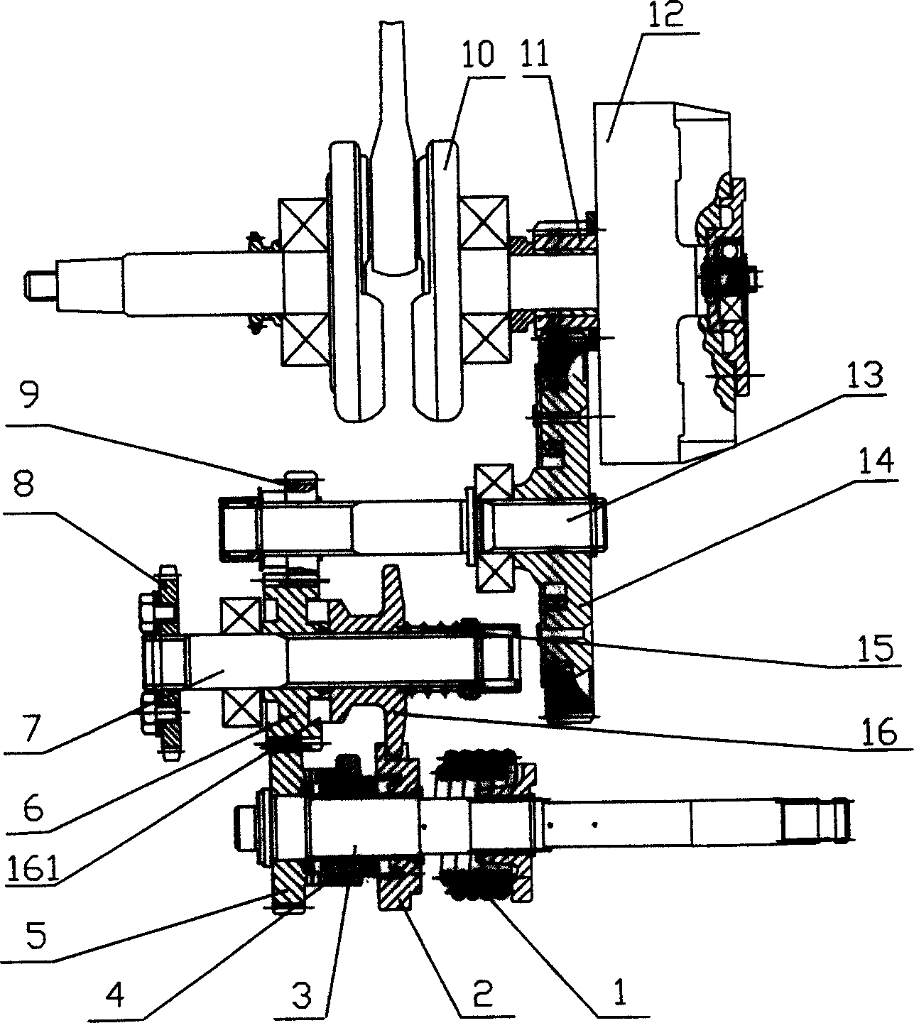
[0014] Such as figure 2 As shown, the engine foot starting structure includes a crankshaft 10, a clutch 12, a main shaft 13, a countershaft 7 and a starting shaft assembly. The crankshaft 10 has a primary driving gear 11 meshing with a primary driven gear 14 on the main shaft 13, and the main shaft 13 A secondary driving gear 9 is also installed on the secondary shaft 7, a secondary driven gear 6 is looped on the secondary shaft 7, and a spline sleeve 16 with flange is also installed on the secondary shaft 7 through a spline, and one is installed on the secondary shaft. The spring 15 on the shaft 7 pushes the spline sleeve 16 to the secondary driven gear 6. The end surface of the spline sleeve 16 opposite to the secondary driven gear 6 has a plurality of protruding claws 161, co...


PUM


Abstract

The foot starting engine structure includes crankshaft, main shaft, auxiliary shaft, and starting shaft assembly. On the main shaft, there are the first stage of driven gear, the second stage of driving gear, and the first driving gear meshed to the first stage of driven gear; and on the auxiliary shaft, there is the second stage of driven gear. The starting shaft assembly includes starting rod, starting gear on the starting rod, ratchet wheel pair and repositioning spring. The second stage of driven gear is meshed with the second stage of driving gear on the main shaft and the starting gear. On the auxiliary shaft, there are spline sleeve with flange and spring to make the spline sleeve and the second stage of driven gear buckle mutually. There is also one end cam slid connected with the spline sleeve flange. The foot starting engine structure is simple, low in cost, less in noise, convenient and reliable.

Description

technical field [0001] The invention relates to an engine structure, in particular to a novel engine kick start structure. Background technique [0002] The kick starting mechanism of known motorcycle engine is as figure 1 As shown, a ratchet 4 and a starter gear 5 are installed on the starting lever 3, and a special starting gear 17 is engaged with the starting gear 5 on the auxiliary shaft 7, and is engaged with the special gear 19 on the main shaft 13 at the same time. Secondary transmission gear transmission gears 18, 20 are also housed on the layshaft 7 and the main shaft 13, so that the transmission between the main shaft 13 and the layshaft 7 is realized when the engine works normally. When kick starting, the starting lever 3 is combined with the starting gear 5 through the pawl of the ratchet 4, and the starting torque is transmitted to the starting gear 17 on the auxiliary shaft 7, and then the main shaft 13 is rotated through the starting gear 17 and the gear 19 o...

Claims


Application Information

Patent Timeline
IPC IPC(8): F02N3/04
Inventor 刘涛
Owner LONCIN MOTOR
Why Eureka
Try Eureka