Electromagnetic relay with spring pushing structure

An electromagnetic relay, push block technology, applied in electromagnetic relays, electromagnetic relay details, relays, etc., can solve problems such as high cycle fatigue, and achieve the effect of solving dynamic spring fatigue

Active Publication Date: 2005-08-10
XIAMEN HONGFA ELECTRIC POWER CONTROLS
View PDF1 Cites 16 Cited by
  • Summary
  • Abstract
  • Description
  • Claims
  • Application Information

AI Technical Summary

Problems solved by technology

Therefore, it can not only meet the design requirements of the specific contact overtravel of the rel

Method used


Image

  • Electromagnetic relay with spring pushing structure
  • Electromagnetic relay with spring pushing structure
  • Electromagnetic relay with spring pushing structure

Examples


Embodiment Construction

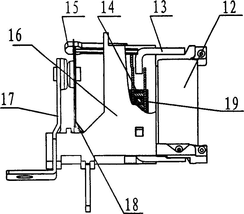
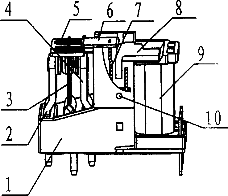
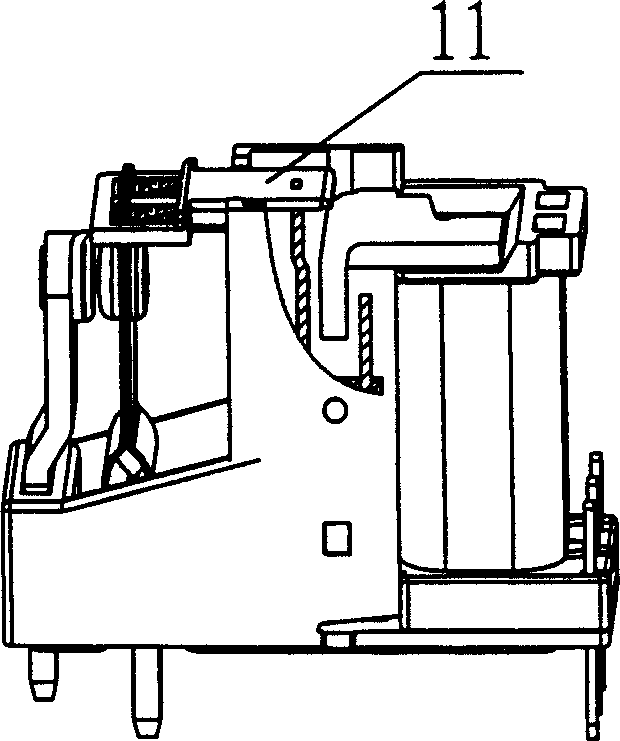
[0019] Such as figure 2 As shown, the present invention (single pole double throw type) consists of a base part, an intermediate mechanism, a magnetic circuit part and a housing. Among them: the base part is assembled by the upper static spring combination 2, the lower static spring combination 4 and the moving spring combination 3 directly inserted into the base 1; the intermediate mechanism is composed of a push block 6 and a spring 5; the magnetic circuit part is composed of a coil 9 , the yoke 8 and the armature combination 7, the coil and the yoke are positioned on the positioning groove of the base by the yoke after being inserted into each other, and the armature combination is positioned on the axis hole of the base by the rotating shaft in the center; the intermediate mechanism is connected by a spring and The combined connection of the movable spring is combined with the armature through the card slot of the part of the pull rod structure under the push block. When...


PUM


Abstract

The disclosed electromagnetic relay is composed of magnetic circuit part static and moving springs and base, and middle mechanism. In magnetic circuit, winding and yoke are positioned on the base. Armature, static and moving springs are setup at the base. The static spring consists of static contact and riveted spring leaves. Moving contact for forming circuital channel is riveted on head part of the moving spring leaves including two pieces of spring leaves riveted. Rivets form bulge structure of positioning springs. The said middle mechanism is composed of promoting block and spring. One end of the spring is installed on bulge structure in window of upper part of the promoting block, and the other end of the spring is installed on bulge structure on combined head of the moving spring. Overtravel of contact is generated by compression deformation of spring, and not generated from deformation of moving spring directly so as to solve problem of high cyclic fatigue of moving spring.

Description

technical field [0001] The invention relates to a magnetic latching relay, in particular to an electromagnetic relay with a spring pushing structure. Background technique [0002] At present, one of the development directions of electronic technology is high reliability, high power, low power consumption, small size, and low cost. As an electromechanical component, magnetic latching relays are widely used in various industrial controls, power systems, office equipment, household appliances, communication equipment, aerospace and other fields. Especially when the magnetic latching relay is working, the permanent magnet in the magnetic circuit part replaces the electromagnetic generated by the coil of the ordinary electromagnetic relay, and the coil does not need to be energized for a long time, so that it has the characteristics of close to "0" power consumption. It is getting higher and higher today, and its application is becoming more and more extensive. [0003] figure...

Claims


Application Information

Patent Timeline
IPC IPC(8): H01H50/56
Inventor 刘金枪
Owner XIAMEN HONGFA ELECTRIC POWER CONTROLS
Why Eureka
Try Eureka