Supercharge Your Innovation With Domain-Expert AI Agents!

Power inverter

A power conversion device and electric conversion technology, applied in the direction of output power conversion devices, circuits, electrical components, etc., can solve the problems of large components, increased number of parts, and increased costs

Inactive Publication Date: 2005-08-10
KK TOSHIBA
View PDF0 Cites 2 Cited by
  • Summary
  • Abstract
  • Description
  • Claims
  • Application Information

AI Technical Summary

Problems solved by technology

[0023] In any case, in order to reduce the inductance, the number of parts will increase and the structure will become complicated
In addition, the increase in the size of the components due to the increase in the capacity of the snubber circuit 5 products, and the increase in the number of parts due to the parallel structure, all constitute the main reasons for the increase in cost.

Method used


Image

  • Power inverter
  • Power inverter
  • Power inverter

Examples


Embodiment Construction

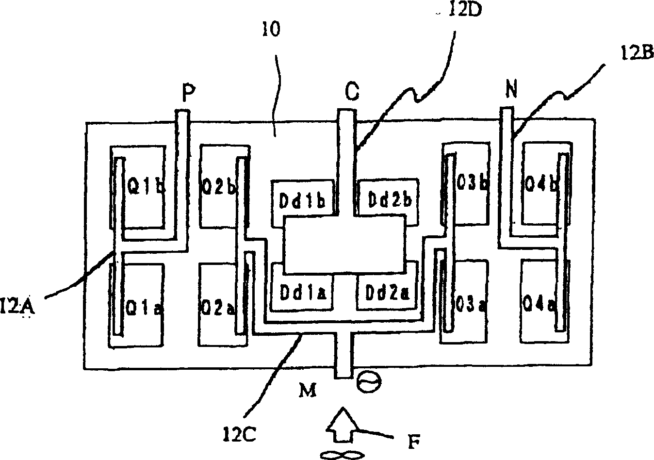
[0044] Embodiments of the present invention are described below. figure 1 It is an arrangement diagram of the semiconductor element Q and the diode Dd on one cooler in the power conversion device according to the first embodiment of the present invention. exist figure 1 In , a circuit of a single-phase part in a forward conversion circuit having a system a and a system b in a 2-column structure is shown.

[0045] Such as figure 1 As shown, each semiconductor element Q is mounted in such a direction that both of its short sides face the wind flow F. As shown in FIG. The first diode Dd1 and the second diode Dd2 with small heat loss are arranged in the central part of the heat receiving part 10, and the system a side is arranged upstream of the wind along the direction of the wind flow F, and the system b is arranged downstream of the wind. That is, the first diode Dd1a of system a is installed on the upstream side of the wind, the first diode Dd1b of system b is installed ...


PUM


Abstract

To provide a power converter. The devices of the power converter are arranged so that the shorter sides of the individual semiconductor devices are oriented directly facing the flow of air. A first diode and a second diode which are low in heat loss are placed in the center of a heat receiving portion, and a second semiconductor device and a third semiconductor device which are high in heat loss are placed on both sides thereof. A first semiconductor device and a fourth semiconductor device lower in heat loss than the above items are placed at both the ends of the heat receiving portion. Thus, the temperature distribution in the heat receiving portion is leveled.

Description

technical field [0001] The present invention relates to a power conversion device which is installed under the chassis of a railway locomotive and uses a semiconductor element. Background technique [0002] Generally, a power conversion device composed of semiconductor elements includes an inverse conversion circuit for converting direct current to alternating current, a forward conversion circuit for converting alternating current to direct current, and the like. There is also a variable voltage variable frequency (VVVF) inverse conversion circuit in the inverse conversion circuit. This VVVF inverse conversion circuit can control the voltage and frequency of the AC output to be variable, and is commonly used in power conversion devices. [0003] For example, in the DC tram of the railway locomotive system, the VVVF inverse conversion circuit is generally used as a power conversion device to convert DC into AC with variable voltage and frequency to control AC induction motor...

Claims


Application Information

Patent Timeline
Patent Type & Authority Applications(China)
IPC IPC(8): H05K7/20H01L23/467H01L25/07H01L25/18H02M1/00H02M7/00H02M7/483H02M7/757
CPCH01L2924/0002
Inventor 宫入正树桥本隆
Owner KK TOSHIBA
Features
  • R&D
  • Intellectual Property
  • Life Sciences
  • Materials
  • Tech Scout
  • Unparalleled Data Quality
  • Higher Quality Content
  • 60% Fewer Hallucinations
Learn More