Substrate applying device

A technology for laminating devices and substrates, which is applied in the directions of contacts, optics, instruments, etc., can solve problems such as substrate pollution, and achieve the effects of avoiding pollution and eliminating static electricity accumulation

Inactive Publication Date: 2005-08-17
HONG FU JIN PRECISION IND (SHENZHEN) CO LTD +1
View PDF0 Cites 0 Cited by
  • Summary
  • Abstract
  • Description
  • Claims
  • Application Information

AI Technical Summary

Problems solved by technology

[0006] In order to overcome the problem that substrate bonding devices in the prior art easily cause substrate contamination when eliminating static electricity, the present invention provides a substrate bonding device that can eliminate static electricity accumulation and at the same time avoid contamination to the substrate

Method used


Image

  • Substrate applying device
  • Substrate applying device
  • Substrate applying device

Examples


Embodiment Construction

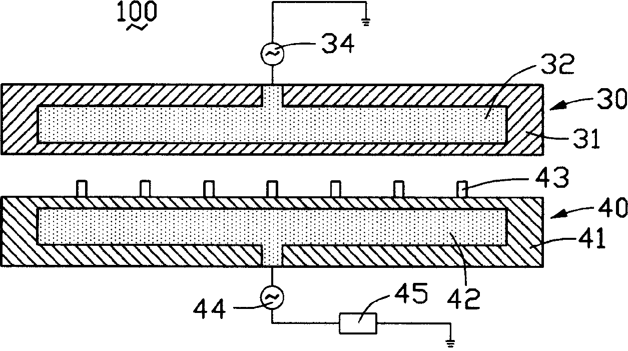
[0012] Such as figure 2 Shown is a cross-sectional view of the substrate laminating device of the present invention. The substrate bonding apparatus 100 includes a first electrostatic chuck 30 , a second electrostatic chuck 40 and a controller 45 .

[0013] The first electrostatic chuck 30 includes a first chuck body 31 , a first electrode 32 disposed in the first chuck body 31 , and a first power source 34 connected to the first electrode 32 . The second electrostatic chuck 40 is disposed on the lower side of the first electrostatic chuck 30 , and includes a second chuck body 41 , a second electrode 42 disposed in the second chuck body 41 and a second power supply connected to the second electrode 42 44 , the second suction cup main body 41 is provided with a plurality of support columns 43 , and the support columns 43 can move up and down relative to the second suction cup main body 41 . The controller 45 is connected to the second power source 44 of the second electrosta...


PUM


Abstract

This invention discloses a base board adhering device including a first static suction cup, a second static suction cup and a controller, said second static suction cup is set under the first cup, said controller is connected with said second cup to control it to generate positive and negative voltages alternately.

Description

【Technical field】 [0001] The invention relates to a substrate processing equipment, in particular to a substrate bonding device. 【Background technique】 [0002] The manufacturing process of the liquid crystal display panel mainly includes the step of laminating two glass substrates in a vacuum environment, so that the two glass substrates form a receiving space that can be filled with liquid crystals. [0003] Because before the vacuum bonding process, a circuit structure has been formed on one of the glass substrates. In the vacuum bonding process, electrostatic protection plays a key role. If the accumulation of static electricity cannot be eliminated in time, it is very likely that the glass substrate will be damaged due to electrostatic discharge. circuit on the circuit, resulting in defective products. [0004] The prior art discloses a substrate bonding device with static elimination function such as figure 1 As shown, the substrate bonding device includes a first el...

Claims


Application Information

Patent Timeline
Patent Type & Authority Applications(China)
IPC IPC(8): G02F1/133G02F1/1333G02F1/1341G02F1/1362H01H1/00
CPCG02F1/136204G02F1/1341G02F2001/133354G02F1/133354
Inventor 江经纬张彦中
Owner HONG FU JIN PRECISION IND (SHENZHEN) CO LTD
Why Eureka
Try Eureka