Ceramic resonator welding machine

A ceramic resonator and plug-in technology, which is applied in the field of automatic welding equipment, can solve the problems of time-consuming and eye-catching

Inactive Publication Date: 2005-08-24
姚剑浩
View PDF0 Cites 10 Cited by
  • Summary
  • Abstract
  • Description
  • Claims
  • Application Information

AI Technical Summary

Problems solved by technology

The ceramic resonator chip is extremely small, only 7.0mm×1.3mm×0.4mm or smaller, and the soldering operation is time-consuming and eye-consuming
There is no report on the resonator automatic welding machine

Method used


Image

  • Ceramic resonator welding machine
  • Ceramic resonator welding machine
  • Ceramic resonator welding machine

Examples


Embodiment Construction

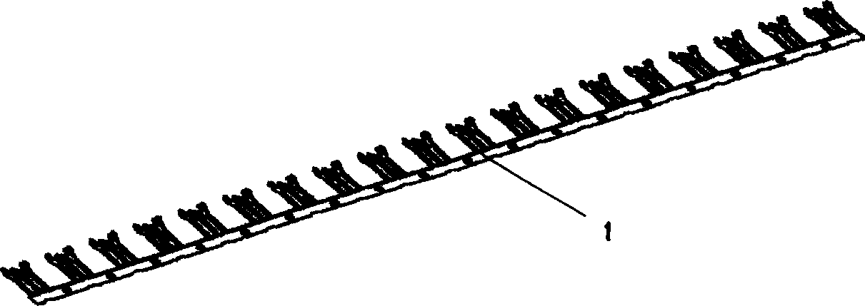
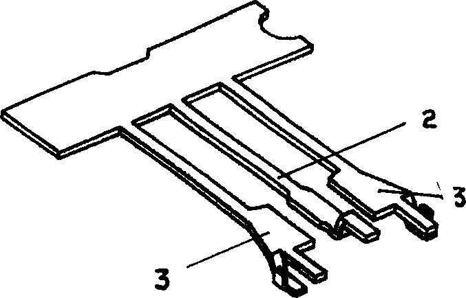
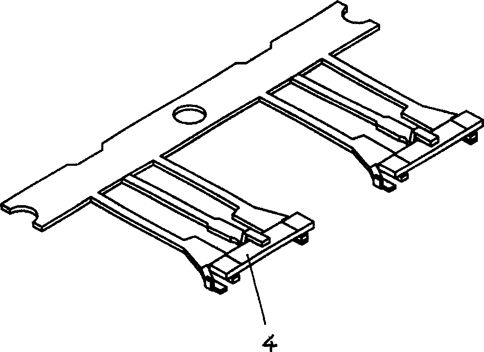
[0027] Such as figure 1 and figure 2 As shown, there are multiple sets of lead wires 1 on the lead wire of the ceramic resonator, and each set of lead wires has three wires, including two side pins 3 and one center pin 2 . Such as image 3 As shown, the task of the ceramic resonator welding machine of the present invention is to insert the ceramic resonator chip 4 into the three leads, and then weld solder on the contact between the center pin and the electrode of the chip.

[0028] The ceramic resonator welding machine includes a chip conveying device, a chip inserting mechanism, a welding device and a lead wire dynamic positioning device. Such as Figure 4 and Figure 5 As shown (for the convenience of expression, in Figure 4 and other several accompanying drawings provide a X-Y-Z three-dimensional coordinates as a frame of reference), the chip conveying device includes a spiral vibrating feeder 5, a linear vibrating feeder 6, a sheet-adding rod 7 and a rotary disc-ty...


PUM


Abstract

A ceramic resonator plugging and soldering machine for plugging the chip is ceramic resonator into leading-wire bar and then soldering it is composed of the chip delivering unit consisting of spiral vibrating delivering device, linear vibrating delivering device, chip feeding rod and rotary disc type chip shifting device, the chip plugging unit consisting of chip holding block and chip plugging rod, the soldering unit, and the dynamic locating unit for leading-wire bar. The PLC is used for data processing and control of all said units.

Description

technical field [0001] The invention relates to automatic welding equipment for ceramic resonator chips and lead wires, and a ceramic resonator welding machine. Background technique [0002] The ceramic resonator chip and the lead are inserted and welded to form a complete resonator. In order to facilitate the soldering operation, multiple groups of resonator lead wires are generally combined into lead bars, and the operator clamps the ceramic resonator chips with a camera, inserts them on the lead bars one by one, and then solders them. The ceramic resonator chip is extremely small, only 7.0mm×1.3mm×0.4mm or smaller, and the soldering operation is time-consuming and eye-consuming. There is no report on the resonator automatic welding machine at present. Contents of the invention [0003] The present invention aims to provide a ceramic resonator welding machine, which can automatically weld ceramic resonator chips to lead bars. [0004] The ceramic resonator welding mac...

Claims


Application Information

Patent Timeline
Patent Type & Authority Applications(China)
IPC IPC(8): B23K3/00B23K3/06B23K3/08B23K37/00H01L21/60
CPCH01L2924/0002
Inventor 姚剑浩
Owner 姚剑浩
Why Eureka
Try Eureka