
Laser light path precollimator

A pre-alignment and optical path technology, applied in the field of laser applications, can solve problems such as reduced work efficiency

Inactive Publication Date: 2005-08-24
SHANGHAI MICRO ELECTRONICS EQUIP (GRP) CO LTD
View PDF0 Cites 6 Cited by
  • Summary
  • Abstract
  • Description
  • Claims
  • Application Information

AI Technical Summary

Problems solved by technology

[0005] The purpose of the present invention is to provide a laser optical path pre-aligner, which solves the technical problem that the existing alignment method needs to use the optical system to perform rough calibration and then fine adjustment, so that the work efficiency is reduced. Using this tool Can greatly reduce the difficulty of optical system installation and adjustment, improve work efficiency

Method used


Image

  • Laser light path precollimator
  • Laser light path precollimator
  • Laser light path precollimator

Examples


Embodiment 1

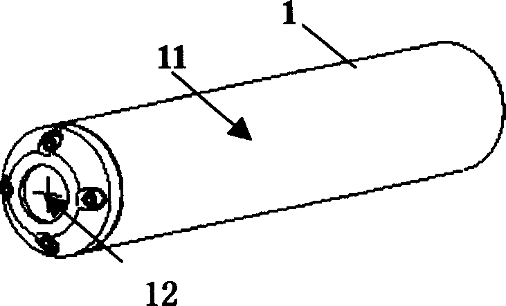
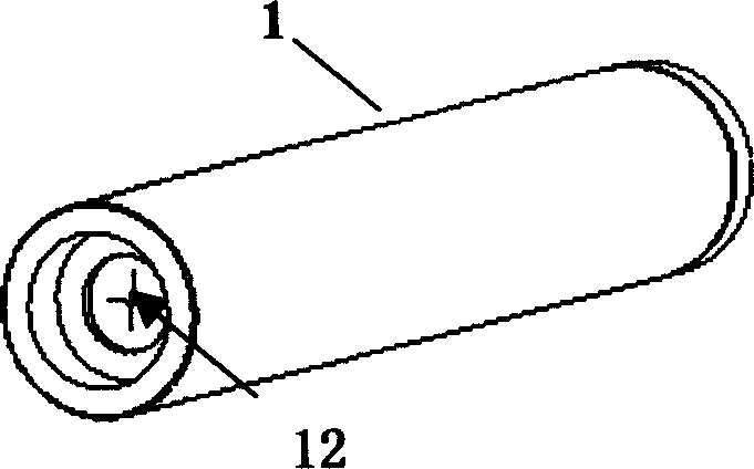
[0023] Embodiment one: crosshair type laser beam pre-aligner (such as figure 1 , 2 );

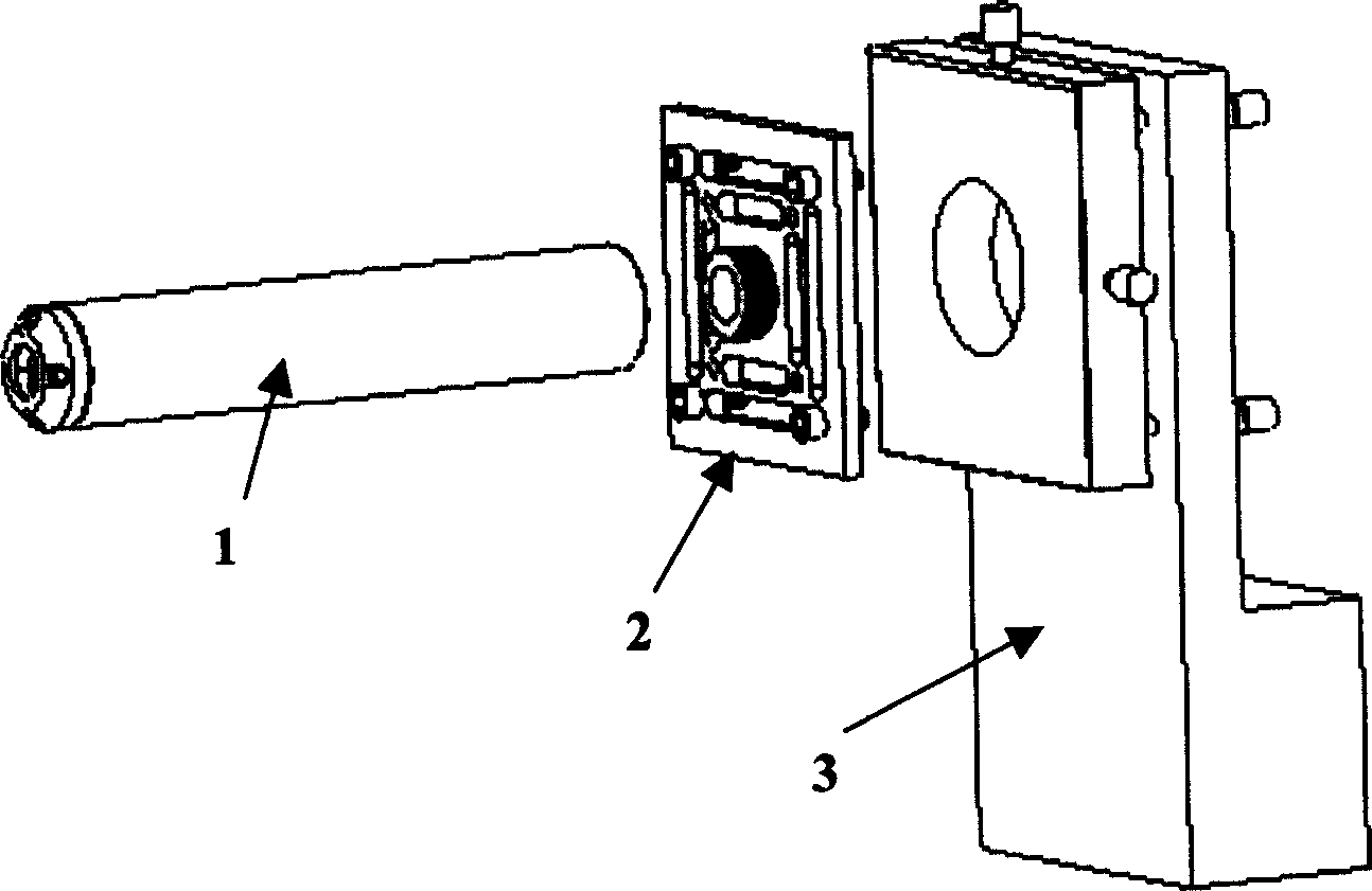
[0024] Such as figure 1 , 2 As shown: a cross wire 12 is respectively arranged at both ends of a section of hollow straight pipe 11 with a certain length. The line connecting the centers of the two cross wires is coincident (or parallel) with the axis of the straight pipe. When using, refer to image 3 : Fix the laser beam pre-aligner 1 on the alignment device 3 via the connection adapter device 2 . Adjust the alignment device so that the beam enters from one end (the center of the beam is located at the intersection of the cross wires as much as possible), and at the other end of the device, observe the degree of overlap of the two cross wires. According to the linear propagation characteristics of light and the principle that two points determine a line, adjust the dimensions of the alignment device. When the two cross wires coincide, the axis of the pre-aligner is basically paralle...

Embodiment 2

[0025] Embodiment two: iris type laser beam pre-aligner (such as Figure 4 );

[0026] Such as Figure 4 As shown: a diaphragm 42 is installed at both ends of a hollow straight tube 41 with a certain length (the adjustment range of the aperture of the diaphragm: 0.8-10mm), and the line connecting the centers of the two diaphragms coincides with the axis of the straight tube (or parallel). When using, refer to Figure 5 : Fix the laser beam pre-aligner 4 on the alignment device 6 via the connection adapter device 5 . The alignment device is adjusted so that the beam passes through one of the apertures, and at the other end of the device a power detector is used to detect the output energy. According to the linear propagation characteristics of light and the principle that two points determine a line, adjust the dimensions of the alignment device. When the detected power is maximum, the axis of the pre-aligner basically coincides with the central optical axis of the laser be...


PUM


Abstract

This invention relates to the laser appliance field, especially the aligning device of laser path. It sets joint spider fibers at two ends of the hollow straight tube, the joint spider fibers are on the surface of the transparent glass, the glass of the input port is transparent, the output is ground glass; the connecting line of the centers of the two joint spider fibers parallel the axes of the straight tube. Or set flare stops at the two ends of the hollow straight tube, the center connecting line of the two flare stop parallel the axes of the straight tube. It mainly solves the problem that the present aligning method makes use of optics system to adjust roughly and then precisely to cause the reduction of the working efficiency. This invention can greatly reduce the difficulty of the adjustment of the optics system and improve the operational efficiency.

Description

technical field [0001] The invention relates to the field of laser applications, in particular to a laser optical path pre-aligner. Background technique [0002] For an optical system, it contains many optical devices, such as: lenses, polarization beam splitters, isolators, gratings, various experimental crystals and optical fibers, etc. The laser light enters the optical system after exiting the light source. All the optical devices in the optical path will affect the propagation direction of the laser beam to varying degrees. The degree of influence depends on the relative position of the optical axis of each optical device relative to the optical axis of the laser beam (horizontal: x, y, pitch: Rx, Ry). This effect will seriously reduce the technical performance of the entire system, and even cause the system to fail to achieve its design function. Therefore, each optical component needs to be aligned during the construction of the optical system. Usually, each device...

Claims


Application Information

Patent Timeline
Patent Type & Authority Applications(China)
IPC IPC(8): G02B27/30
Inventor 刘畅
Owner SHANGHAI MICRO ELECTRONICS EQUIP (GRP) CO LTD
Learn More