Method for manufacturing metal shield

A metal shielding and electroforming technology, which is applied in the direction of metal layered products, magnetic field/electric field shielding, chemical instruments and methods, etc., to achieve the effect of no internal stress, high resolution and integrity

Inactive Publication Date: 2005-08-24
U TECH MEDIA
View PDF0 Cites 8 Cited by
  • Summary
  • Abstract
  • Description
  • Claims
  • Application Information

AI Technical Summary

Problems solved by technology

[0004] Therefore, the main purpose of the present invention is to provide a method for manufacturing metal shields in combination with yellow light and electroforming processes, so as to solve the above-mentioned known problems in the manufacture of high-resolution metal-plated shields.

Method used


Image

  • Method for manufacturing metal shield
  • Method for manufacturing metal shield
  • Method for manufacturing metal shield

Examples


Embodiment Construction

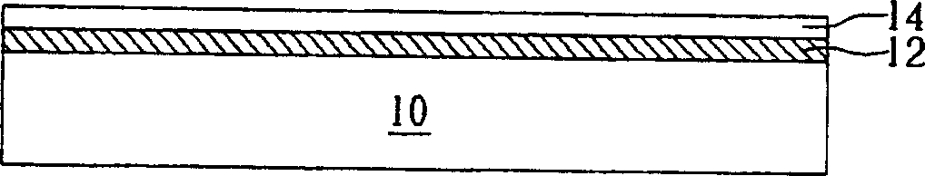
[0012] refer to Figure 1 to Figure 6 , Figure 1 to Figure 6 Schematic diagram of the process of the method for fabricating a high-resolution metal shield of the present invention. Such as figure 1 As shown, firstly, a cleaned substrate 10 is provided, and the material of the substrate 10 can be glass or other materials. Next, a release layer 12 is formed on the surface of the substrate 10 to make the subsequent metal shielding finished product easy to release from the surface of the substrate 10 . In this embodiment, the release layer 12 is a layer of positive or negative film photoresist material, and the thickness is not limited.

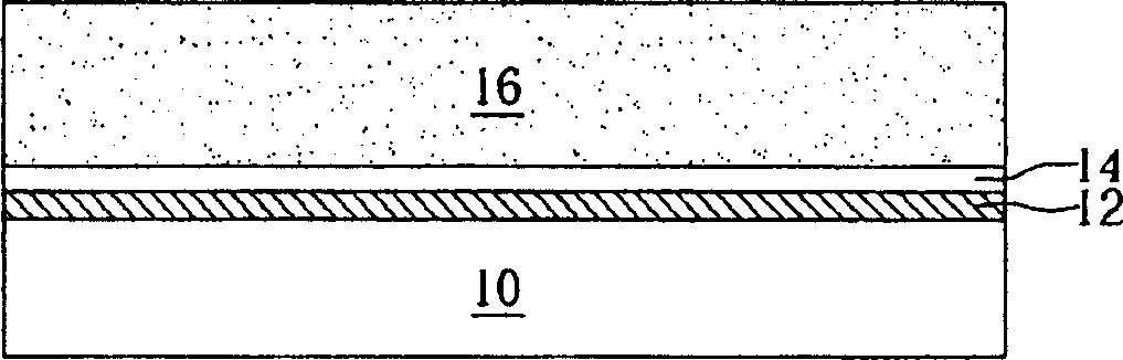
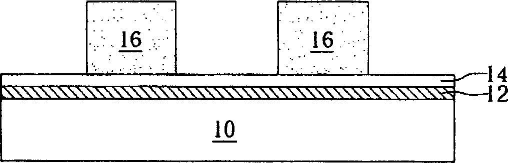
[0013] Next, a thin film metal layer 14 is formed on the surface of the release layer 12, and the thin film metal layer 14 is used as an electroforming seed layer for helping the electroforming metal object adhere and grow in the subsequent electroforming process. Wherein, the formation methods of the thin film metal layer 14 include methods ...


PUM


Abstract

This invention discloses a method for making the metal shield. Firstly provide a basal board, next form a releasing layer, a electroforming crystal kind layer and a graphical light-obstructing layer. Thereinto the light-obstructing layer is used to limit the graphics of the metal shield, and expose part of the electroforming crystal kind layer. Then do a electroforming procedure to form the metal shield on the exposed electroforming crystal kind layer. Finally do a doffing mould procedure to make the metal shield disengage from the basal board.

Description

technical field [0001] The invention provides a method for manufacturing a metal shield, especially a method for manufacturing a metal shield with high resolution by using exposure and development technology and mold release technology. Background technique [0002] Metal shielding is one of the process tools commonly used in semiconductor, packaging, micro-electromechanical, and stamper processes. It can be combined with techniques such as evaporation, sputtering, screen printing, and solder ball printing for flip-chip packaging to form the required structure. Generally speaking, metal shielding is to first make the required openings on a specific position of a metal sheet to form a specific pattern, and then when the above-mentioned evaporation and other processes are performed, the material passes through the openings on the metal sheet and is deposited on the substrate. form a specific graph. Among them, the pattern of the metal shielding is mostly produced by mechanic...

Claims


Application Information

Patent Timeline
Patent Type & Authority Applications(China)
IPC IPC(8): B32B15/04H05K9/00
Inventor 陈怡礽周天佑赖志辉陈怡发张世慧
Owner U TECH MEDIA
Why Eureka
Try Eureka