Vacuum solar transduction heat pipe structured in all glass body case and manufacturing method

A production method and all-glass technology, applied in the field of solar energy applications, can solve the problems of low yield, low efficiency, and easy breakage.

Inactive Publication Date: 2005-08-31
徐宝安
0 Cites 29 Cited by

AI-Extracted Technical Summary

Problems solved by technology

The all-glass vacuum heat collecting tubes have defects such as scaling, freezing cracks and single tube damage, the entire solar water heater is paralyzed and the heat starts slowly.
The heat pipe solar vacuum heat collector has defects such as high production cost, fouling, difficu...

Abstract

A vacuum solar heat exchanging tube of glass consists closed of glass shell container, heat tube. Its preparing process includes forming glass shell container with one opening end and one closed end, packaging heat collecting tube set in tube container, attaching heat absorption plate on heat absorption section being connected to heat discharging section through transit connecting neck, charging heat exchanging agent of phase transition, welding electrode, having the set vacuumed and setting relevant nuts and seal surfaces.

Application Domain

Solar heating energySolar heat devices +2

Technology Topic

Tubing setPhase transition +5

Image

  • Vacuum solar transduction heat pipe structured in all glass body case and manufacturing method
  • Vacuum solar transduction heat pipe structured in all glass body case and manufacturing method
  • Vacuum solar transduction heat pipe structured in all glass body case and manufacturing method

Examples

  • Experimental program(1)

Example Embodiment

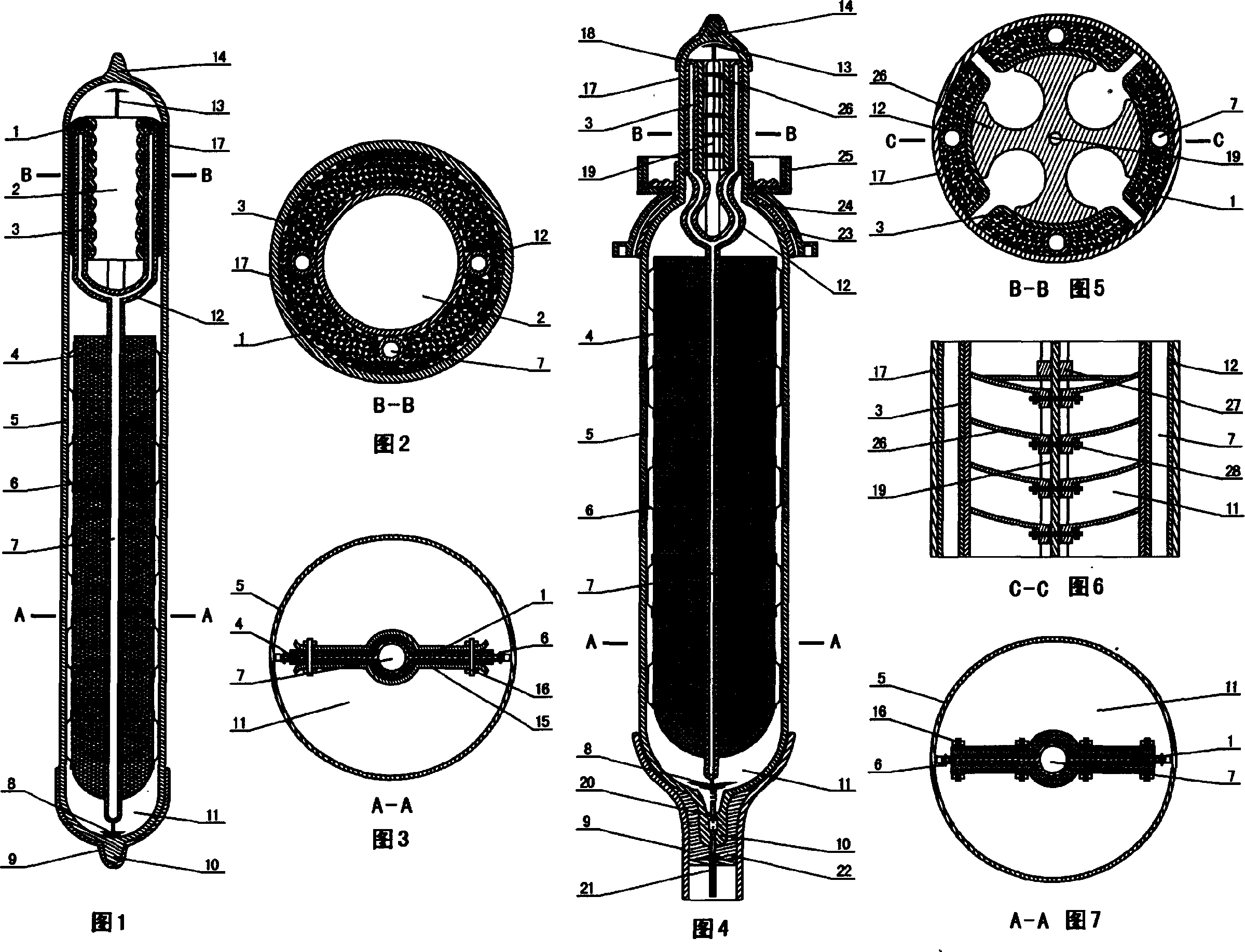
[0111] Figure 1, Figure 2, and Figure 3 form the first embodiment: an all-glass vacuum solar heat transfer heat pipe with an outer shell, which mainly consists of two parts, one part is an all-glass enclosed container shell and the other part is a heat pipe. The all-glass tube used in the embodiment is an all-glass shell formed by welding the glass shell 5 of the heat absorption section of the glass heat collection tube and the glass tube 17 of the heat release section of the glass heat collection tube. Heat conduction particles 1, heat release section of heat pipe 2, heat conduction particles heat pipe metal container 3, heat absorption plate 4, glass shell 5 of the heat absorption section of the glass heat collection tube, heat pipe support elastic card 6, heat pipe cavity 7, heat absorption end protection of the heat pipe Cover 8, glass heat-collecting tube heat-absorbing section protective cap 9, glass heat-collecting tube protective cap bonding sealant 10, heat pipe throat wall 12, and getter 13 are combined to form a heat pipe, which is integrally encapsulated in a full glass shell glass In the vacuum chamber 11 of the heat collection tube, the two ends of the glass heat collection tube are arc-shaped. The heat-absorbing section of the heat pipe is provided with a heat-absorbing plate 4, and the heat-absorbing plate 4 and the round glass tube 5 are separated by a heat pipe supporting elastic card 6 and do not contact the glass tube 5. The heat conduction device of the heat release section of the heat pipe is a heat-conducting particle heat pipe metal container 3, which is combined with the heat release section 2 of the glass heat collection tube to form the heat release section of the all-glass vacuum solar heat transfer heat pipe of the outer shell. The heat conduction particle heat pipe metal container 3 is a metal bomb The shrinking bellows tightly presses the heat-conducting particles 1 on the conducting surface of the heat-releasing glass. The sealing end of the heat pipe can be provided with a protective cover, and the end of the heat releasing section of the heat pipe is fixed with a getter. A getter 13 is fixed on the protective cover at the end of the heat pipe. The top of the heat release section of the vacuum heat collection tube is provided with a glass heat collection tube exhaust tail pipe seal 14. The bottom of the heat absorption section of the vacuum heat collection tube is equipped with a glass heat collection tube arc ball head. In order to enhance the strength of the heat release section of the arc ball head, the glass heat collection tube cap is bonded with sealant 10 to protect the heat absorption part of the glass heat collection tube The cap 9 is bonded to the tube.
[0112] Fig. 4, Fig. 5, Fig. 6, and Fig. 7 constitute the second embodiment: an all-glass vacuum solar heat transfer heat pipe with an outer shell, which is composed of an all-glass enclosed container shell, a heat pipe, a glass-sealed conductive electrode, and the like. The shell is a non-equal diameter round glass tube, the heat absorption section is a metal heat pipe evaporation section and a composite carbon material plate, and the heat release section is a metal heat pipe condensing section. The metal fan-shaped cavity container containing the carbon particle heat-conducting material is bolted to the metal elastic plate. The sheet is closely attached to the glass tube to radiate heat, a glass sealing static resistance scale electrode is installed, and a sealing and locking device is installed. The all-glass tube used in the embodiment is an all-glass shell formed by welding the thick round glass tube 5 in the heat absorption section of the glass heat collection tube and the thin round glass tube 17 in the heat release section of the glass heat collection tube. Heat pipe heat release section thermally conductive particle metal container 3, positioning pin 19, heat pipe heat absorption plate 4, glass heat collection tube heat absorption section glass shell 5, heat pipe support elastic card 6, heat pipe cavity 7, heat pipe heat absorption tail end protective cover 8 、Glass heat-collecting tube heat-absorbing section protective cap 9, glass heat-collecting tube protective cap bonding sealant 10, heat pipe throat wall 12, getter 13 combined with each other to form a heat pipe, and the whole is encapsulated in a full glass shell glass heat-collecting tube vacuum Cavity 11. The glass at the tube wall 12 of the heat pipe throat corresponds to the connection part of the seal, and the vacuum gap between the throat of the glass heat collection tube and the throat of the heat pipe makes the heat release section and the connection fixing device have good thermal insulation conditions to prevent the heat release section of the tube from dissipating heat Conducted to the fastening element. The throat sealing sheath flange 23 of the glass heat collection tube is sealed and combined with the throat part of the glass heat collection tube and the sheath flange 23 through the glass heat collection tube throat sheath sealant 24 to form the throat sealing sheath method of the glass heat collection tube The flange plate, the sealing sheath flange fastening nut 25 and the glass heat collecting pipe throat sealing sheath flange are combined to form a housing all-glass vacuum solar heat transfer heat pipe fastening assembly. The heat-absorbing tail end protective cover 8 of the heat pipe is electrically connected to the electrical connection wire of the heat pipe, and the glass heat collecting pipe made of glass beads fired on the metal tungsten wire is sealed by glass welding and the metal glass sealing electrode 20 is sealed. The glass heat collecting tube cap electrode insulating sealant 22, the glass heat collecting tube heat absorption section protective cap 9 and the glass sealing electrode connector 21 are glued and sealed to form an electrical connection plug for the protective cap at the end of the glass shell of the heat collecting tube. A protective cover can be provided at both ends of the sealing of the heat pipe, and a getter is fixed at the end of the heat releasing section of the heat pipe. A getter 13 is fixed on the protective cover at the end of the heat pipe. The top of the heat release section of the vacuum heat collection tube is provided with a glass heat collection tube exhaust tail pipe seal 14. In order to enhance the strength of the heat release section, a glass heat collection tube heat release section protective cap 18 is provided.
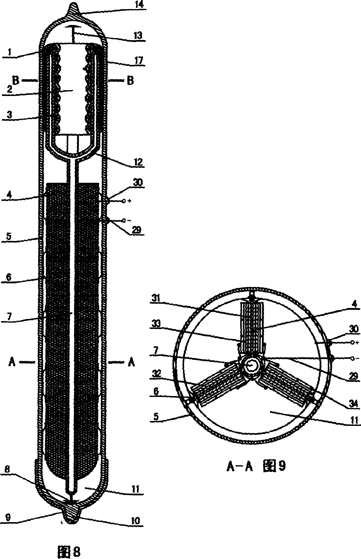
[0113] Figure 8, Figure 2, Figure 9, Picture 10 , Picture 11 Composition of the third embodiment: an all-glass vacuum solar heat exchange heat pipe with an all-glass shell, which is composed of an all-glass enclosed container shell, a heat pipe, a photovoltaic cell, and the like. The glass shell 5 of the heat absorption section of the glass heat collection tube and the glass shell 17 of the heat release section of the glass heat collection tube are equal-diameter round glass tubes, and the heat absorption section is a metal heat pipe evaporation section. The battery P-shaped semiconductor 32, the photovoltaic cell N-shaped semiconductor 33, and the photovoltaic cell negative electrode 34 are composed of photovoltaic panels. The heat release section is a metal heat pipe condensing section through a corrugated elastic metal ring cavity container 3 containing a thermally conductive material 1. The glass tube 17 closely fits and releases heat. Others are equivalent to the first embodiment.
[0114] Figure 12, Figure 13, Figure 14 constitute the fourth embodiment: the outer shell is all-glass vacuum solar heat transfer heat pipe, the heat-absorbing section glass shell 5 of the glass heat-collecting tube heat-absorbing section of the all-glass enclosed container shell, the glass shell 17 of the heat-releasing section of the glass heat collecting tube, the heat pipe And other composition. The shell is a round glass tube glass heat collecting tube heat absorption section glass shell 5 and oval glass tube glass heat collection tube heat release section glass shell 17 welded type, the heat absorption section is a metal heat pipe evaporation section composite carbon material heat pipe heat absorption plate 4, heat release The condensing section of the metal heat pipe passes through the metal cylindrical cavity container containing the heat-conducting particles 1 through the bolt locking metal spring compression and tightly fitting the glass tube to release heat. Others are equivalent to the first embodiment.
[0115] Figure 13, Figure 15, Figure 16, Figure 17 constitute the fifth embodiment: the outer shell all-glass vacuum solar heat transfer heat pipe, the all-glass enclosed container shell glass heat collecting tube heat absorption section glass shell 5, glass heat collecting tube heat release section glass shell 17. Heat pipe and other components. The outer shell is a round glass tube glass heat collecting tube heat absorption section glass shell 5 and an oval glass tube glass heat collecting tube heat release section glass shell 17 welded type, the heat absorption section is a heat pipe heat absorption plate 4 composite photovoltaic panel, and an electrode glass seal is installed The contact point 30 is glass-sealed and lead-out electrode 29 is glass-sealed and lead-out. The heat release section is a metal heat pipe condensing section through the metal cylindrical cavity container containing the thermally conductive particles 1 through the bolt locking metal spring compression and the glass tube tightly fitting to release heat. Others are equivalent to the first embodiment.
[0116] Figure 13, Figure 15, Figure 18, Figure 19 constitute the sixth embodiment: the outer shell is all-glass vacuum solar heat transfer heat pipe, the all-glass enclosed container shell glass heat collecting tube heat absorption section glass shell 5, glass heat collecting tube heat release section glass shell 17. Heat pipe and other components. The shell is a round glass tube and an oval glass tube welded type, the heat absorption section is a heat pipe heat absorption plate 4 composite photovoltaic panel, and an electrode glass sealing joint 30 is installed with a glass sealing lead-out glass sealing lead electrode 29. The heat release section is a metal heat pipe condensing section through the metal cylindrical cavity container containing the thermally conductive particles 1 through the bolt locking metal spring 38 compression and tightly fitting the glass tube to release heat, and is equipped with a sealing and locking device. Others are equivalent to the first embodiment.
[0117] Figure 20, Figure 21, Figure 22, Figure 23 , Figure 24 Composition of the seventh embodiment: the outer shell is all-glass vacuum solar heat transfer heat pipe, the outer shell is a non-equal diameter round glass tube, the metal heat pipe evaporation section multi-rib tube metal fin heat pipe heat absorption plate 4 composite photovoltaic panel, installed with glass sealing points 30. The glass seal leads the electrode 29; the heat release section is a metal heat pipe condensation section. The multi-condensation tube passes through the longitudinal corrugated elastic heat conduction particle heat pipe metal container 3 which contains the heat conduction particles 1 to elastically shrink and closely fit the glass tube to release heat; equipped with installation Sealing and locking device. Others are equivalent to the first embodiment.
[0118] Figure 25 , Figure 26, Figure 27, Figure 28, Figure 29 Composition of the eighth embodiment: the shell is all-glass vacuum solar heat transfer heat pipe, the shell is equal-diameter round glass tube, the metal heat pipe evaporation section multi-rib tube cross metal fin heat pipe heat absorption plate 4 composite photovoltaic panel, installed with glass sealing points 30. The glass-sealed lead electrode 29; the heat-releasing section is a metal heat pipe. The condensing section passes through the petal-shaped elastic heat-conducting particle heat pipe metal container 3 that contains the heat-conducting particles 1. The metal container 3 elastically shrinks and closely fits the glass tube to release heat, and is equipped with a sealing and locking installation. Device. Others are equivalent to the first embodiment.
[0119] Figure 30, Figure 13, Figure 32, Figure 31 constitute the ninth embodiment: the shell is all-glass vacuum solar heat transfer heat pipe, the shell is a round glass tube and an oval glass tube welded type, and the heat absorption section is a metal heat pipe evaporation section metal fin The heat pipe heat absorbing plate 4 is a composite photovoltaic panel, and is equipped with a glass sealing joint 30 and a glass sealing lead electrode 29. The heat release section is a metal heat pipe condensing section through the metal cylindrical cavity container containing the thermally conductive particles 1 through the bolt locking metal spring compression and the glass tube tightly fitting to release heat. A suction cup sealing and locking device composed of a protective cap suction cup connecting rod 45, a suction cup support 46, and a polymer suction cup 47 is provided, and the non-light facing surface is a reflector 54. Others are equivalent to the first embodiment.
[0120] Figure 34, Figure 32, Figure 33, Figure 35 constitute the tenth embodiment: the shell is all-glass vacuum solar heat transfer heat pipe, the shell is a round glass tube and an oval glass tube welded type, and the heat absorption section is a metal heat pipe evaporation section metal fin The heat pipe heat absorption plate 4 is a composite carbon material and a photovoltaic battery panel, and is equipped with a glass sealing joint 30 and a glass sealing lead electrode 29. The heat release section is a metal heat pipe. The condensing section passes through the metal cylindrical cavity container containing the thermally conductive particles 1 and is tightly attached to the glass tube through bolt locking and metal spring compression. The outer wall of the glass shell 17 of the glass heat-emitting section passes through the thermally conductive particles 1 It is sleeved with the quartz glass tube 51 and installed with a glass sealing static resistance scale electrode. Equipped with a suction cup sealing and locking device, and its non-light facing surface is a reflective mirror surface. Others are equivalent to the first embodiment.
[0121] Figure 36, Figure 37, Figure 38, Figure 39, Figure 40 constitute the eleventh embodiment: the shell is all-glass vacuum solar heat transfer heat pipe, the shell is a non-equal diameter round glass tube, and the heat absorption section is the metal heat pipe evaporation section composite carbon Material plate, the heat release section is a metal heat pipe. The condensing section passes through a metal fan-shaped cavity containing heat conduction particles 1. The heat conduction particle heat pipe. The metal container 3 is tightly locked with the glass shell 17 of the heat release section of the glass heat collecting pipe through a temperature-controlled bimetal elastic plate. Laminated heat release, the outer wall of the glass shell 17 of the heat release section of the glass heat collection tube is sleeved with the quartz glass tube 51 through the heat-conducting particles 1, and a glass sealing static resistance scale electrode is installed, and a sealing and locking device is installed. Others are equivalent to the second embodiment.
[0122] Fig. 41, Fig. 42, Fig. 43, Fig. 44, Fig. 45, and Fig. 46 constitute the twelfth embodiment: the shell is all-glass vacuum solar heat transfer heat pipe, and the shell is welded with non-equal diameter round glass tube, and the heat absorption section is made of metal The metal tube in the evaporation section of the heat pipe is composited with carbon material and photovoltaic panels, and is equipped with a glass sealing joint 30 and a glass sealing lead electrode 29. The heat release section is a metal heat pipe. The condensing section passes through a metal cylindrical cavity containing heat conduction particles 1. The heat conduction particle heat pipe metal container 3 passes through the heat conduction particle container cap 53 and the top core compresses the heat conduction particles 1 tightly with the glass shell 17 of the heat release section of the glass collector tube. The heat is released by bonding, and the outer wall of the glass shell 17 of the heat release section of the glass heat collecting tube is sleeved with the quartz glass tube 51 through a carbon material, and an end cap sealing and locking device is provided. Others are equivalent to the first embodiment.
[0123] Figure 47 , Figure 42, Figure 43, Figure 48, Figure 49 , Figure 50 Composition of the thirteenth embodiment: the shell is all-glass vacuum solar heat transfer heat pipe, the shell is a non-equal diameter round glass tube welding type, the heat absorption section is the metal heat pipe evaporation section, the metal tube composite carbon material and the photovoltaic panel, and the glass seal is installed The contact 30, the glass sealing lead electrode 29. The heat release section is a metal heat pipe. The condensing section passes through a metal cylindrical cavity containing heat conduction particles 1. The heat conduction particle heat pipe metal container 3 passes through the heat conduction particle container cap 53 and the top core compresses the heat conduction particles 1 tightly with the glass shell 17 of the heat release section of the glass collector tube. Laminated heat release, the outer wall of the glass shell 17 of the heat release section of the glass heat collecting tube is sleeved with the quartz glass tube 51 through a carbon material, and a glass sealing static resistance scale electrode is installed. Equipped with end cap sealing and locking device. Others are equivalent to the second embodiment.
[0124] Figure 51 , Figure 42, Figure 43, Figure 52, Figure 53 , Figure 54 Composition of the fourteenth embodiment: the shell is all-glass vacuum solar heat transfer heat pipe, the shell is a non-equal diameter round glass tube welding type, the heat absorption section is three metal heat pipes, the evaporation section, the metal tube composite carbon material and the Y-shaped structure of the photovoltaic panel, Equipped with a glass sealing lead electrode. The heat release section is a metal heat pipe. The condensing section passes through a metal cylindrical cavity containing heat conduction particles 1. The heat conduction particle heat pipe metal container 3 passes through the heat conduction particle container cap 53 and the top core compresses the heat conduction particles 1 tightly with the glass shell 17 of the heat release section of the glass collector tube. Laminated heat release, the outer wall of the glass shell 17 of the heat release section of the glass heat collecting tube is sleeved with the quartz glass tube 51 through a carbon material, and a glass sealing static resistance scale electrode is installed. Equipped with expanded diameter top tight sealing device. Others are equivalent to the second embodiment.
[0125] Figure 55 , Figure 13, Figure 56 constitute the fifteenth embodiment: the shell is all-glass vacuum solar heat transfer heat pipe, the shell is non-equal diameter round glass tube welding type, the heat absorption section is the metal heat pipe evaporation section, composite carbon material and photovoltaic cells, installed There are glass sealing points 30 and glass sealing lead electrodes 29. The glass shell 5 of the heat absorption section of the round glass heat collection tube is equipped with a reflector 54; the heat release section is a metal heat pipe condensing section through a metal cylindrical cavity containing heat conduction particles 1. The heat conduction particle heat pipe metal container 3 is compressed and compressed by a bolt locking metal spring The glass tube fits closely to release heat. Or equipped with a sealing and locking device. Others are equivalent to the first embodiment.
[0126] Figure 58 , Figure 32, Figure 57 constitute the sixteenth embodiment: the shell is all-glass vacuum solar heat transfer heat pipe, the shell is a round glass tube and an oval glass tube welded type, the heat absorption section is a metal heat pipe evaporation section metal fin composite carbon material and For the photovoltaic panel, the glass shell 5 of the heat absorption section of the round glass heat collecting tube of the elliptical shell is equipped with a reflector 54; a glass sealing point 30 and a glass sealing lead electrode 29 are installed. The heat release section is a metal heat pipe. The condensing section passes through a metal cylindrical cavity containing heat conduction particles 1. The heat conduction particle heat pipe. The metal container 3 is tightly fitted with the glass tube through bolt locking and metal spring compression. The glass heat collection tube heat release section glass shell 17 The outer wall is sleeved with the quartz glass tube 51 through a carbon material, and a glass sealing static resistance scale electrode is installed. Equipped with end cap sealing and locking device. Others are equivalent to the second embodiment.
[0127] Figure 59 , Figure 60 , Figure 61 The seventeenth embodiment of the composition: the shell is all-glass vacuum solar heat transfer heat pipe, the shell is a round glass tube and a rectangular glass tube welding type, the metal heat pipe evaporation section is a multi-rib tube metal fin composite photovoltaic panel, and a glass sealing joint 30 is installed. , The glass sealing leads to the electrode 29. The heat release section is a metal heat pipe condensing section with multiple condensing pipes through the longitudinal corrugated elastic heat conduction particle heat pipe metal container 3 containing heat conduction particles 1 that elastically shrinks and closely fits the glass tube to release heat; a top pressure installation sealing and locking device is provided. Others are equivalent to the first embodiment.
[0128] Figure 62, Figure 63, Figure 64, Figure 65 constitute the eighteenth embodiment: the shell is all-glass vacuum solar heat transfer heat pipe, the shell is a round glass tube and a rectangular glass tube welding type, the rectangular glass heat collector tube heat absorption section glass shell 5 The non-light-facing surface is a reflector 54, a metal heat pipe evaporation section, a multi-rib tube metal fin composite photovoltaic panel, and a glass sealing point 30 and a glass sealing lead electrode 29 are installed. The heat release section is a metal heat pipe. The condensation section of the multi-condensation tube passes through a longitudinal elastic metal groove containing heat conduction particles 1. The heat conduction particle heat pipe. The metal container 3 is locked by a bimetallic sheet 26. Heat release; equipped with top pressure installation sealing and locking device. Others are equivalent to the first embodiment.
[0129] Figure 66 It is a schematic diagram of the structure of a rotating glass lathe with dual fixtures and the same part.
[0130] Figure 66 Middle: The glass lathe consists of outer shaping scraper 55, scraper lock 56, glass tube lock 57, lock truck head 58, lathe rail 60, lathe rail 61, glass tube stable rotating head 62, rocking handle 63, bearing bracket 64, concentric sliding Connecting rod 65, lathe transmission gear box 66, transmission gear 67, torch 68, transmission gear box 69, transmission gear 70, electric motor 71, transmission shaft 72, power gear 73, passive gear 74, bearing 75, internal shaping scraper head clamp 76. Internal plastic scraper head 77, lock truck head 78, internal plastic scraper 79, glass tube lock card 80, torch head 82, etc. Figure 66 Connection composition. The round or oval glass tubes 59, 81 of different pipe diameters can be welded at the same speed. The glass lathe is a double-chuck 80, 57 synchronous rotating lathe, and the lathe rotates through the concentric sliding connecting rod 65 to synchronously drive the driving gear 70, 67 Rotating, at least one of the fronts 78 or 58 is a movable front, the heated torch front 82 is placed between the two fronts 78, 58, the scraper and the mold 55 are installed on the torch front 82, and the clamps 78, 58 can be installed at the rear The distance adjustable rotary positioning device 62 is used to stabilize the glass tube 59 to be welded. On the glass lathe, there is a scraper 79 for leveling the welded joints in the glass tube 81, and a scraper 55 for leveling the welded joints on the outside of the glass tube. Under the action of the two scrapers 79 and 55, the two glass tubes 81 with different diameters and shapes , 59 evenly welded together.

PUM

no PUM

Description & Claims & Application Information

We can also present the details of the Description, Claims and Application information to help users get a comprehensive understanding of the technical details of the patent, such as background art, summary of invention, brief description of drawings, description of embodiments, and other original content. On the other hand, users can also determine the specific scope of protection of the technology through the list of claims; as well as understand the changes in the life cycle of the technology with the presentation of the patent timeline. Login to view more.
Why Eureka
Try Eureka