Optical module and camera module

A technology of optical modules and optical parts, which is applied to cameras, focusing devices of cameras, optics, etc., can solve the problems of changing the shape of the lens driving device, no freedom of shape design, and no freedom of shape design of stepping motors, and achieves the suppression of Power loss, the effect of ensuring movement accuracy

Inactive Publication Date: 2005-08-31
SEIKO INSTR INC
View PDF1 Cites 5 Cited by
  • Summary
  • Abstract
  • Description
  • Claims
  • Application Information

AI Technical Summary

Problems solved by technology

[0009] However, in the structure of such a cylindrical stepping motor, the relationship of disposing the rotor inside the cylindrical stator cannot be broken, and the stepping motor has no degree of freedom in shape design.
Accordingly, the lens driving device equipped with a barrel-type stepping motor has no degree of freedom in shape design, so the lens driving device (optical module) is not suitable for the limited assembly space in the thin electronic instrument in which it is assembled. change shape

Method used


Image

  • Optical module and camera module
  • Optical module and camera module
  • Optical module and camera module

Examples


Embodiment Construction

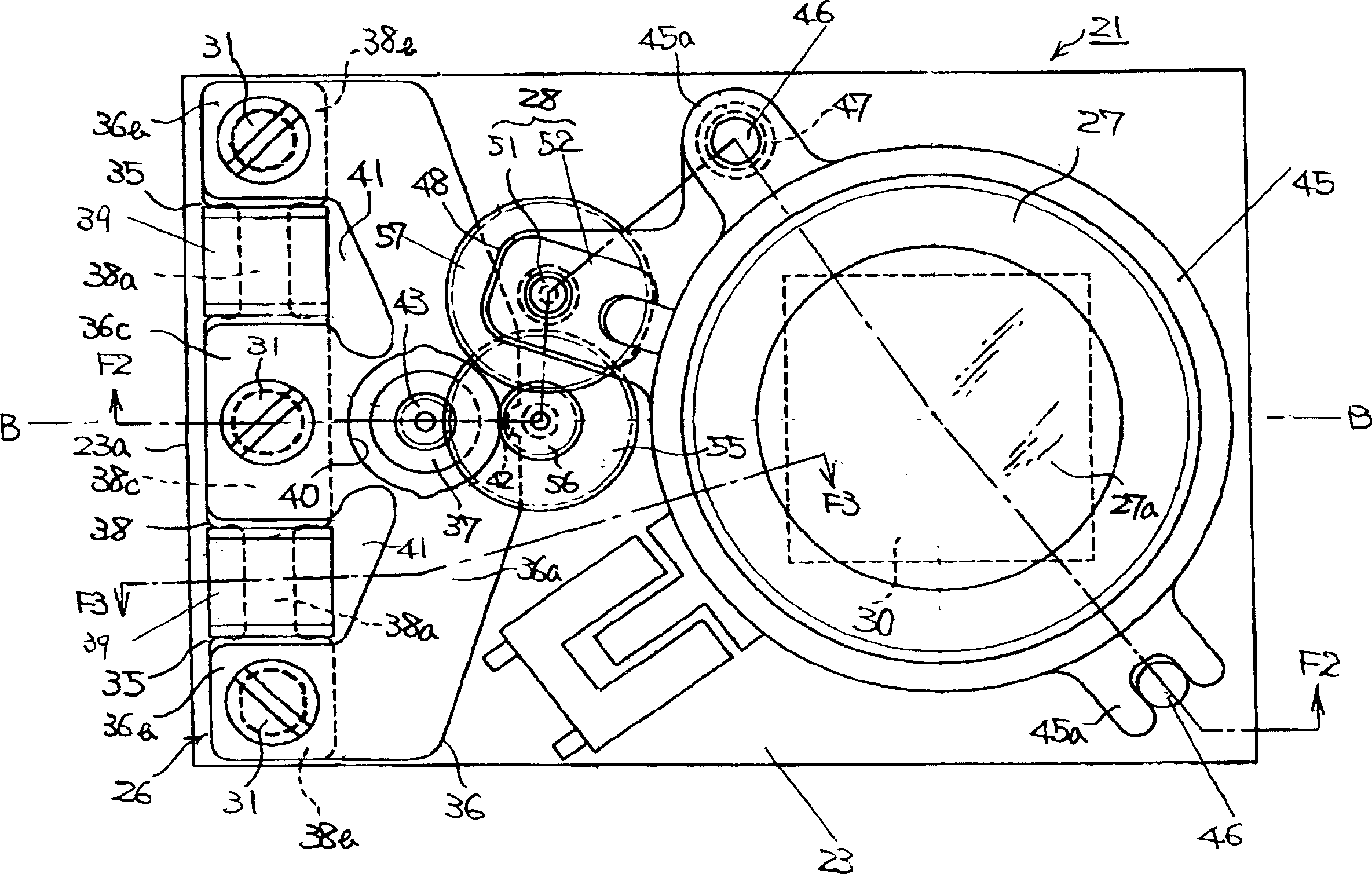
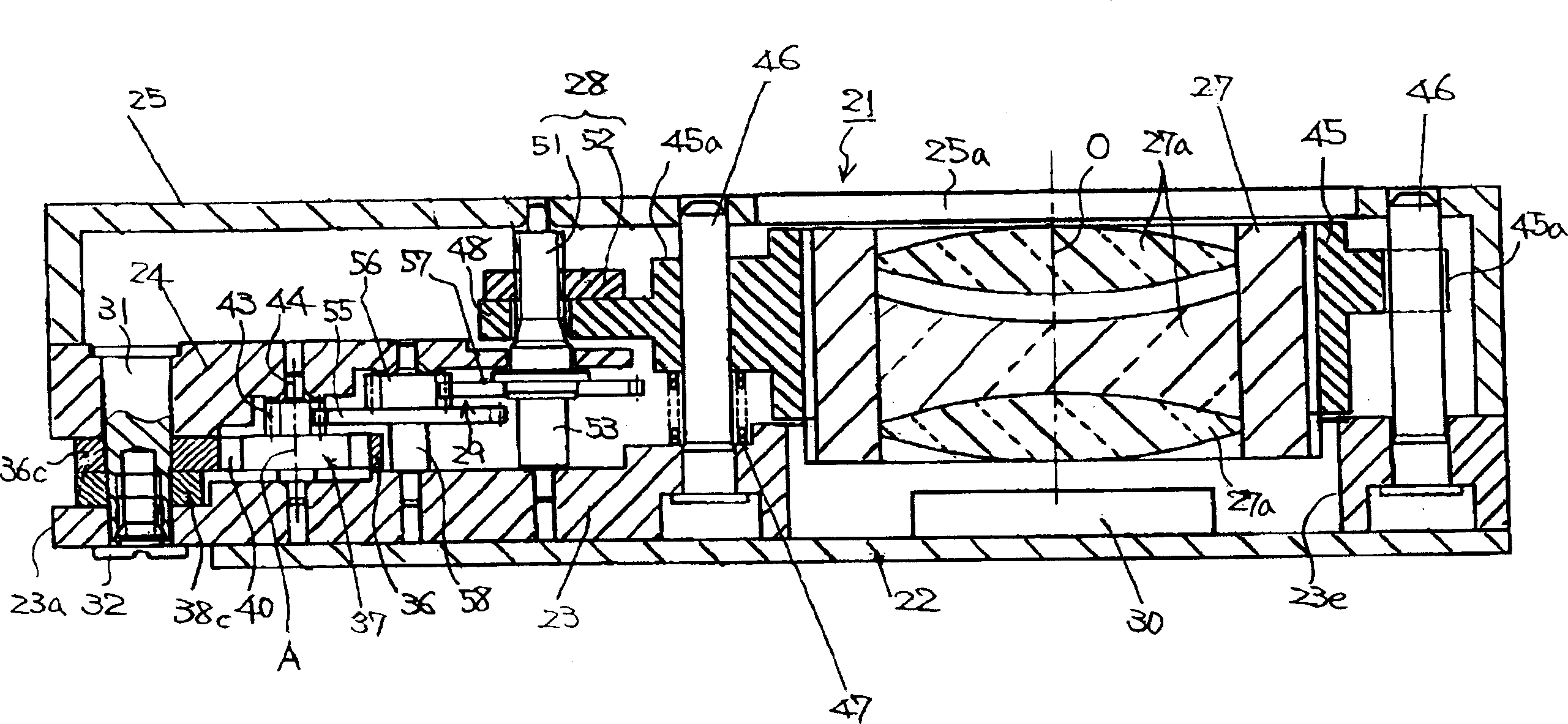
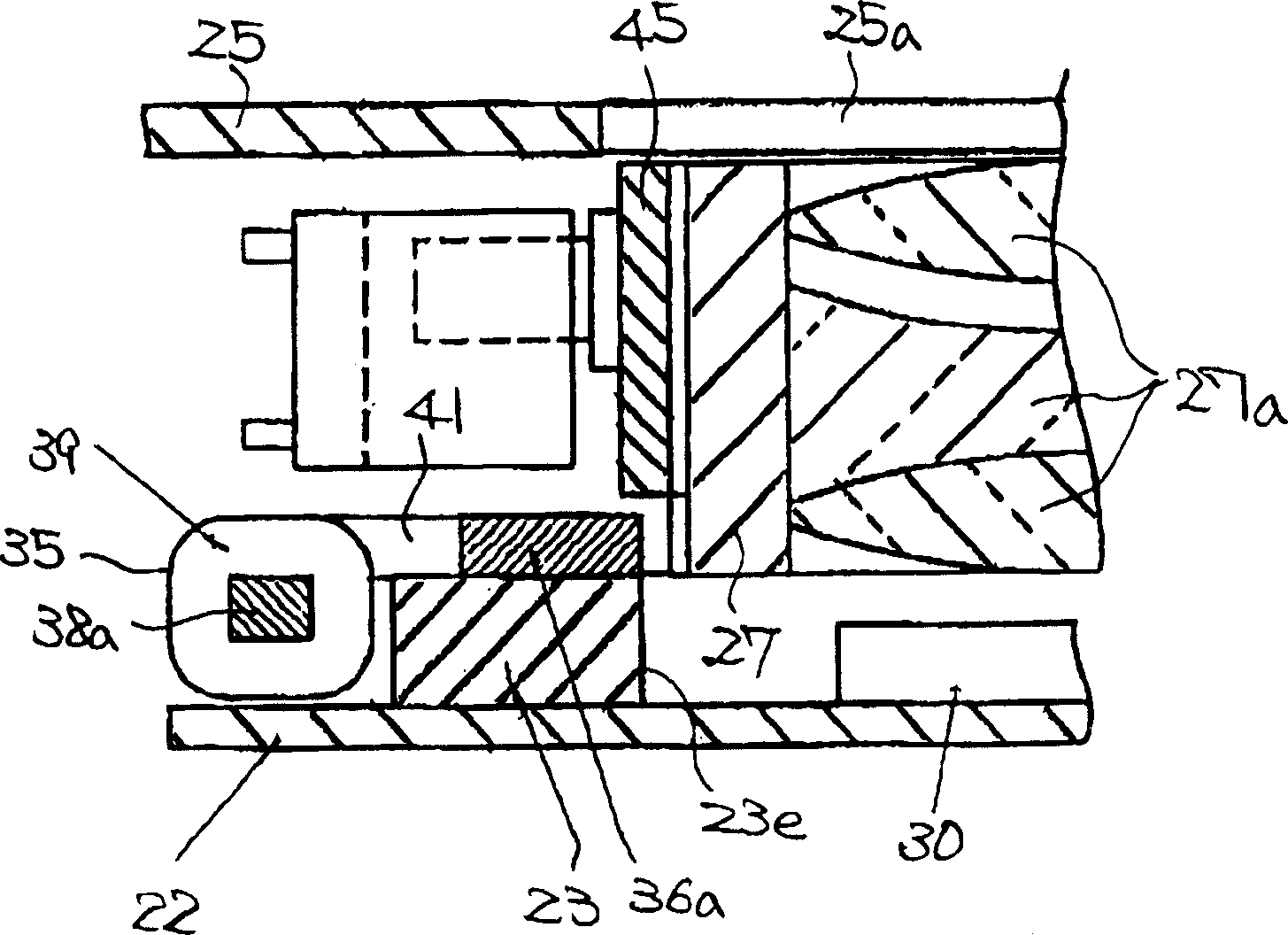
[0050] refer to Figure 1 to Figure 4 The first embodiment of the present invention will be described.

[0051] figure 1 and figure 2 An optical module denoted by reference numeral 21 , for example, a lens driving device, is mounted on a thin electronic device such as a card-type digital camera or a mobile phone with a camera function. This lens driving device 21 includes: a circuit board 22, a bottom plate 23, a gear holder 24, a cover 25, a stepping motor 26, optical components such as a lens barrel 27, a moving mechanism 28, and a reduction gear train 29 as a gear train.

[0052] The circuit board 22 is a hard plate, and an imaging element 30 such as a CCD or CMOS is mounted on one surface thereof. A bottom plate 23 is bonded to the above-mentioned one surface of the circuit board 22 . The bottom plate 23 has a rectangular shape, for example, and has a hole 23e at one end in the longitudinal direction for accommodating the imaging element 30 and allowing the lens barr...


PUM


Abstract

Provided is an optical module that is thin, allows freedom of design in configuration, and assures the accuracy of movement of an optical part while suppressing power loss. A stepping motor 26 and a lens barrel 27 that is moved by moving means 28 are positioned offset from each other along a base plate 23 , and the optical axis of the lens barrel 27 and the axis of a rotor 37 provided in the stepping motor 26 are arranged in parallel with each other on one surface of the base plate 23 . Further, a reduction gear train 29 , which operatively couples the rotor 37 and the moving means 28 together, is arranged on the one surface. The stepping motor 26 consists of a flat-shaped motor equipped with: coil blocks 35 each having an excitation coil 39 horizontally mounted along the base plate 23 ; a yoke 36 whose magnetic path portion 36 a excluding end portions 36 b and 36 c connected with the coil blocks 35 is provided so as not to overlap the coil blocks 35 ; and the rotor 37 arranged within a rotor pass-through hole 40 of the yoke 36.

Description

technical field [0001] The present invention relates to an optical module provided with optical components that move for focus adjustment, zooming, etc., and particularly relates to an optical module suitable for mounting on a thin electronic device, such as a card-type digital camera or a mobile phone with a camera function, and the like. camera module. Background technique [0002] In the past, the following lens driving device (optical module) is known, that is, in order to move the lens barrel holding the lens to adjust the focus, the drive shaft of the cylindrical stepping motor is formed with a feed screw, and the drive shaft is moved from The protruding rack member of the lens barrel holder that supports the lens barrel is engaged with the feed screw, and as the stepping motor rotates in the forward and reverse directions, the lens barrel is moved along the optical axis via the rack member to perform focusing ( For example, refer to Patent Document 1). [0003] In a...

Claims


Application Information

Patent Timeline
Patent Type & Authority Applications(China)
IPC IPC(8): G02B7/02G02B7/04G02B7/08G02B7/10G02B15/14G03B3/10G03B13/32H02K37/16
CPCG02B7/102G02B7/08H02K37/16
Inventor 里馆贵之长谷川春彦铃木诚久米章
Owner SEIKO INSTR INC
Why Eureka
Try Eureka