Method for interconnecting multiple printed circuit boards

A technology of printed circuit boards and connectors, which is applied in the field of connecting several orthogonally arranged printed circuit boards to achieve the effect of shortening the signal transmission distance

Inactive Publication Date: 2005-08-31
FOXCONN (KUNSHAN) COMPUTER CONNECTOR CO LTD +1
View PDF6 Cites 5 Cited by
  • Summary
  • Abstract
  • Description
  • Claims
  • Application Information

AI Technical Summary

Problems solved by technology

None of the existing connectors can meet this requirement

Method used


Image

  • Method for interconnecting multiple printed circuit boards
  • Method for interconnecting multiple printed circuit boards
  • Method for interconnecting multiple printed circuit boards

Examples


Embodiment Construction

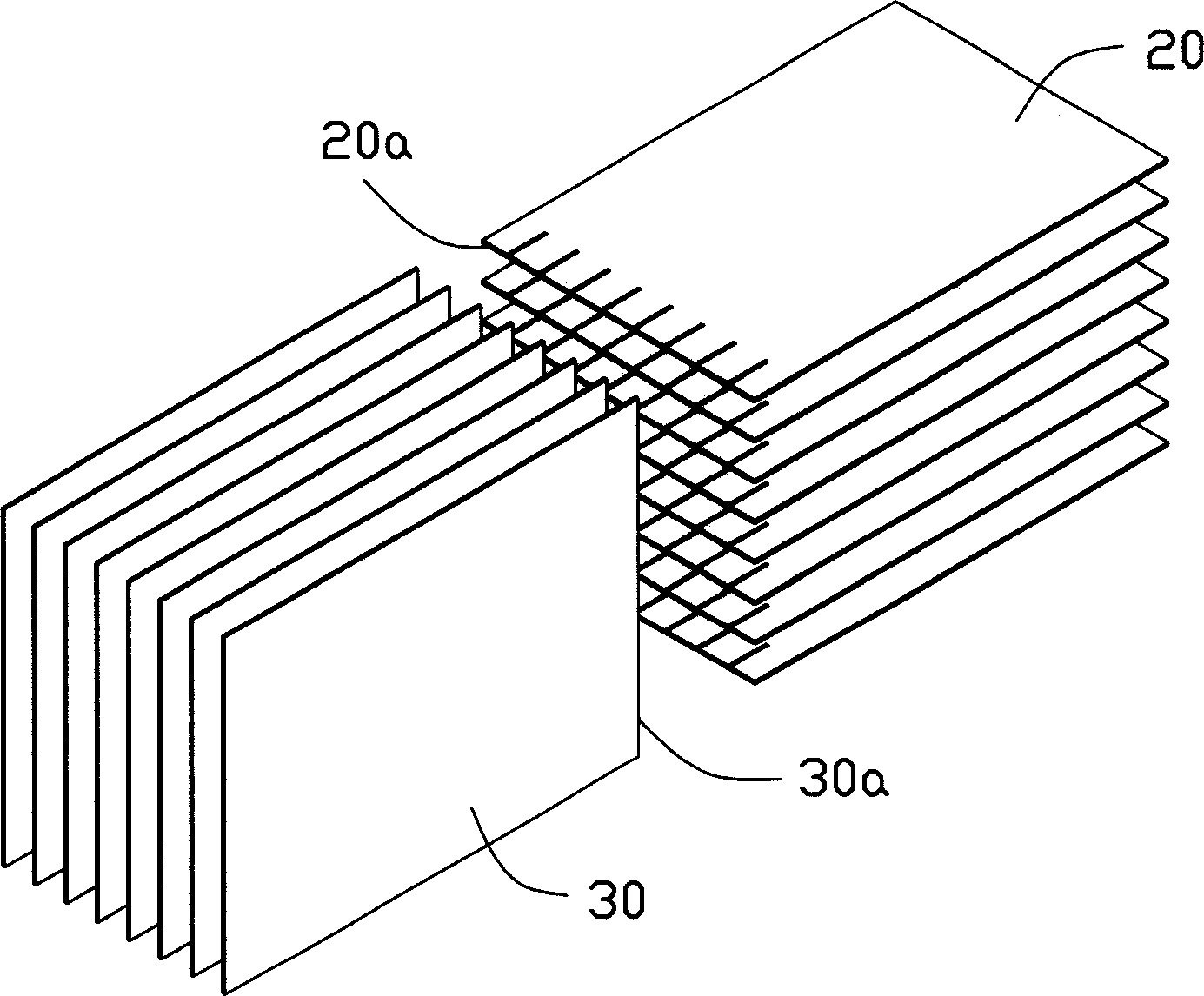
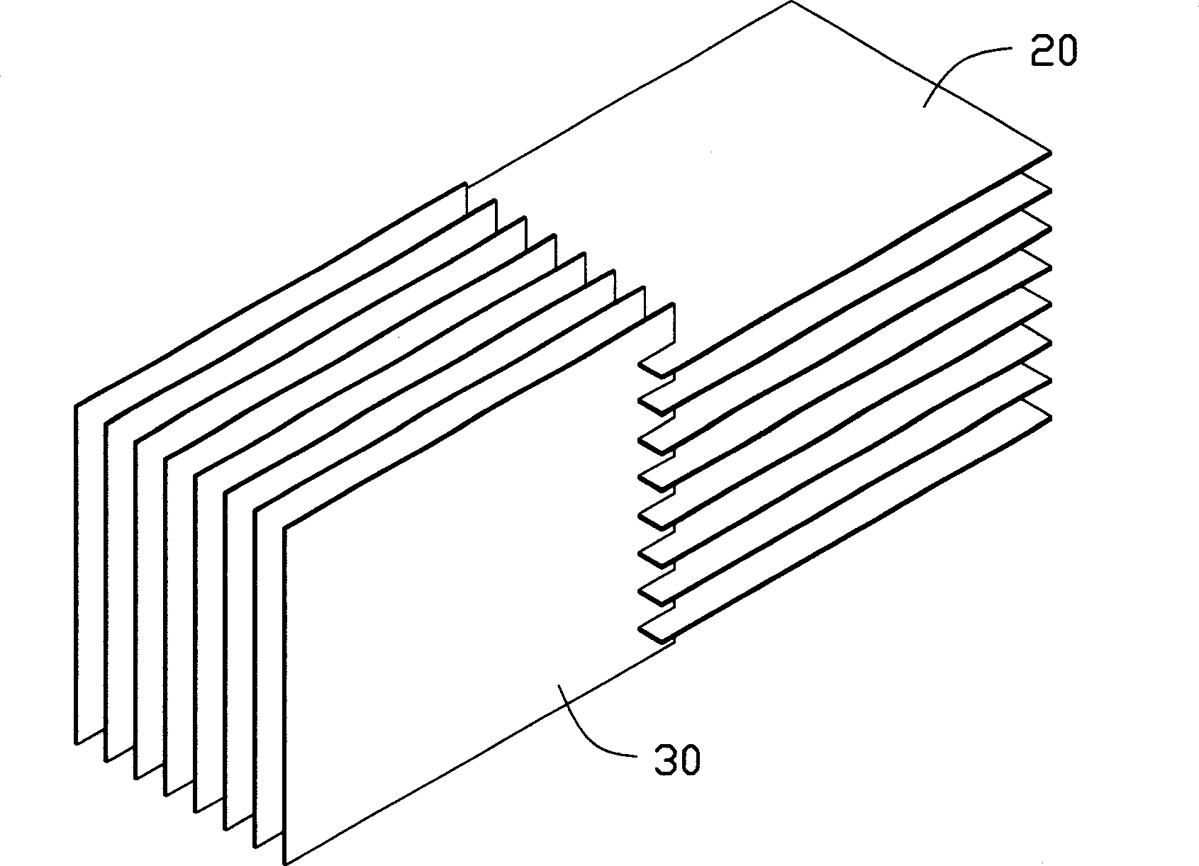
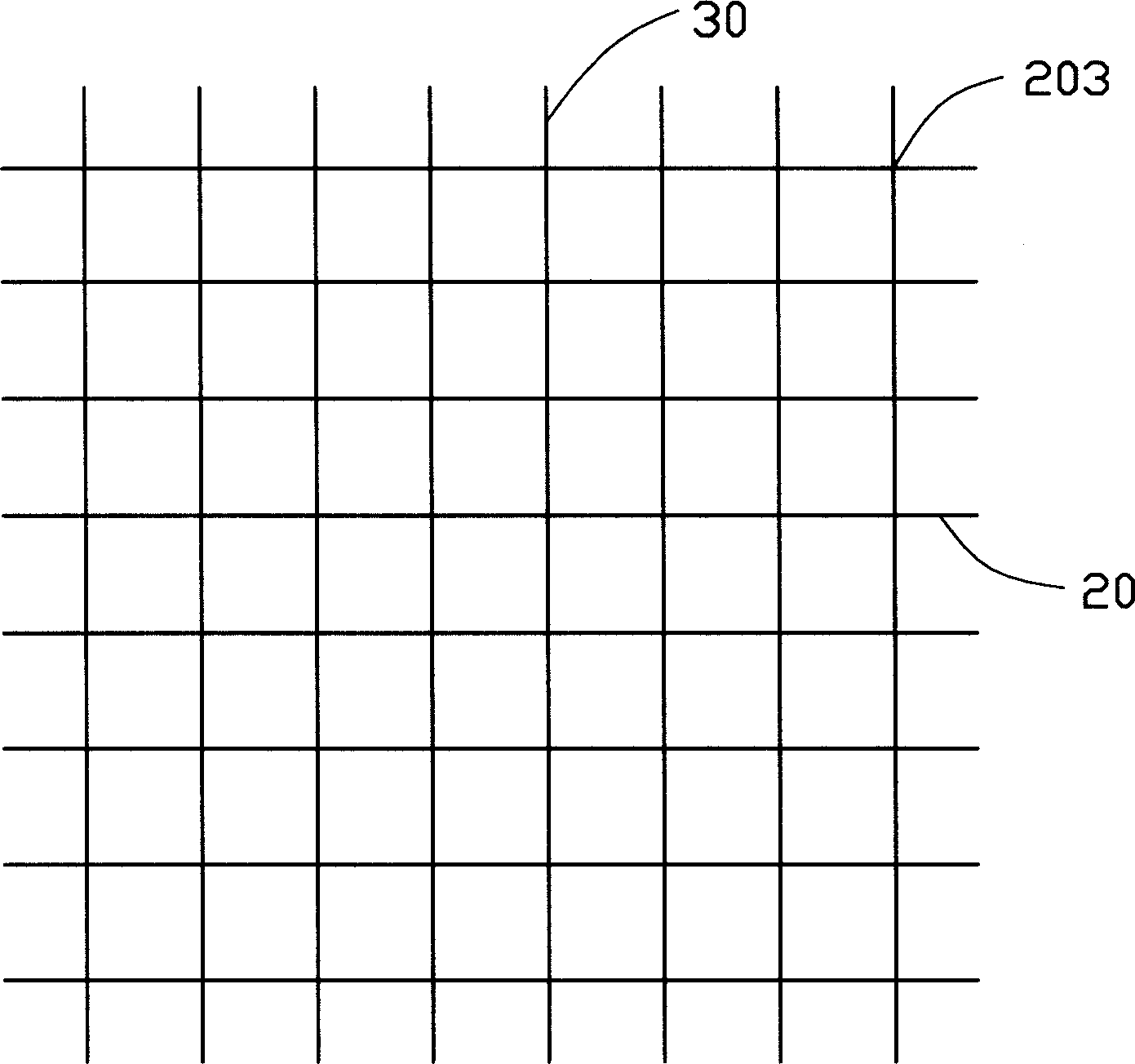
[0040] See figure 1 , figure 2 and image 3 As shown, several horizontal boards 20 (ie, the first printed circuit board) and vertical boards 30 (ie, the second printed circuit board) intersect each other to form a number of connection points or nodes 203 between the two. For ease of explanation, the horizontal plate 20 is referred to as a "fixed plate", and the vertical plate 30 is referred to as a "movable plate".

[0041] See Figure 4 and Figure 5 As shown, the electrical connector 1 in the present invention is used to electrically connect the fixed plate 20 and the movable plate 30. The electrical connector 1 includes an insulating body 10 provided with a plurality of accommodating slots 11 and a plurality of movable terminals 12 received in the accommodating slots 11, wherein the accommodating slots 11 are located on the mating surface 10a of the insulative housing 10 and adjacent to the mating surface 10a. Between the mounting surface 10b. The terminal 12 moves relative to...


PUM


Abstract

A method for electrically interconnecting two printed circuit boards includes the steps of: providing a first printed circuit board (20); providing a second printed circuit board (30); providing a receiving slot (22) in one of the first and the second printed circuit boards such that the first and the second printed circuit boards are orthogonally intersected with each other; and providing at least one electrical connector (1) adjacent the receiving slot and in electrical connection with the first and the second printed circuit boards.

Description

【Technical Field】 [0001] The present invention relates to a method of connecting a plurality of printed circuit boards, and more particularly to a method of connecting a plurality of printed circuit boards arranged orthogonally. 【Background technique】 [0002] Various electronic systems, especially radio communication systems, servers and switches, include a large number of components mounted on printed circuit boards (such as daughter boards and mother boards). The mother board connected to the daughter board is usually called a backplane due to its fixation. The connector that removably assembles the daughter board to the mother board is called a backplane connector. The mother board and the daughter board are connected through electrical connectors to transmit signals and power in the system. [0003] Generally, motherboards and backplanes are printed circuit boards installed in servers or switches, which are connected to several backplane connectors. Each daughter board is pr...

Claims


Application Information

Patent Timeline
Patent Type & Authority Applications(China)
IPC IPC(8): H01R12/16H01R12/71H05K3/00
Inventor 约瑟夫·R·考桑斯盖卢松青
Owner FOXCONN (KUNSHAN) COMPUTER CONNECTOR CO LTD
Why Eureka
Try Eureka