Electronic parts installation device

A technology for electronic component installation and electronic components, applied in the direction of electrical components, electrical components, etc., can solve problems such as insufficient efficiency of installation operations, and achieve the effect of further increasing efficiency and saving space

Active Publication Date: 2005-08-31
JUKI CORP
View PDF1 Cites 9 Cited by
  • Summary
  • Abstract
  • Description
  • Claims
  • Application Information

AI Technical Summary

Problems solved by technology

[0008] However, in the above-mentioned operation control, if the mounting time of one head unit is longer than the receiving time of the electronic component of the other head unit, the other head unit will have a waiting time, and there is a problem that the efficiency of the mounting work is insufficient.

Method used


Image

  • Electronic parts installation device
  • Electronic parts installation device
  • Electronic parts installation device

Examples


Embodiment Construction

[0036] --Overall structure of the embodiment--

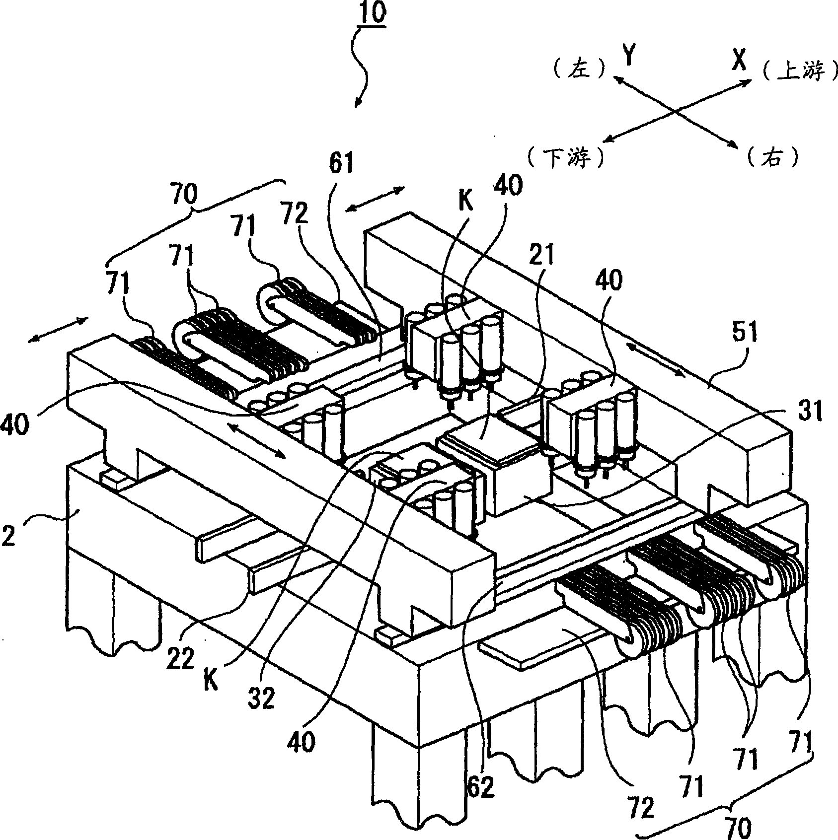
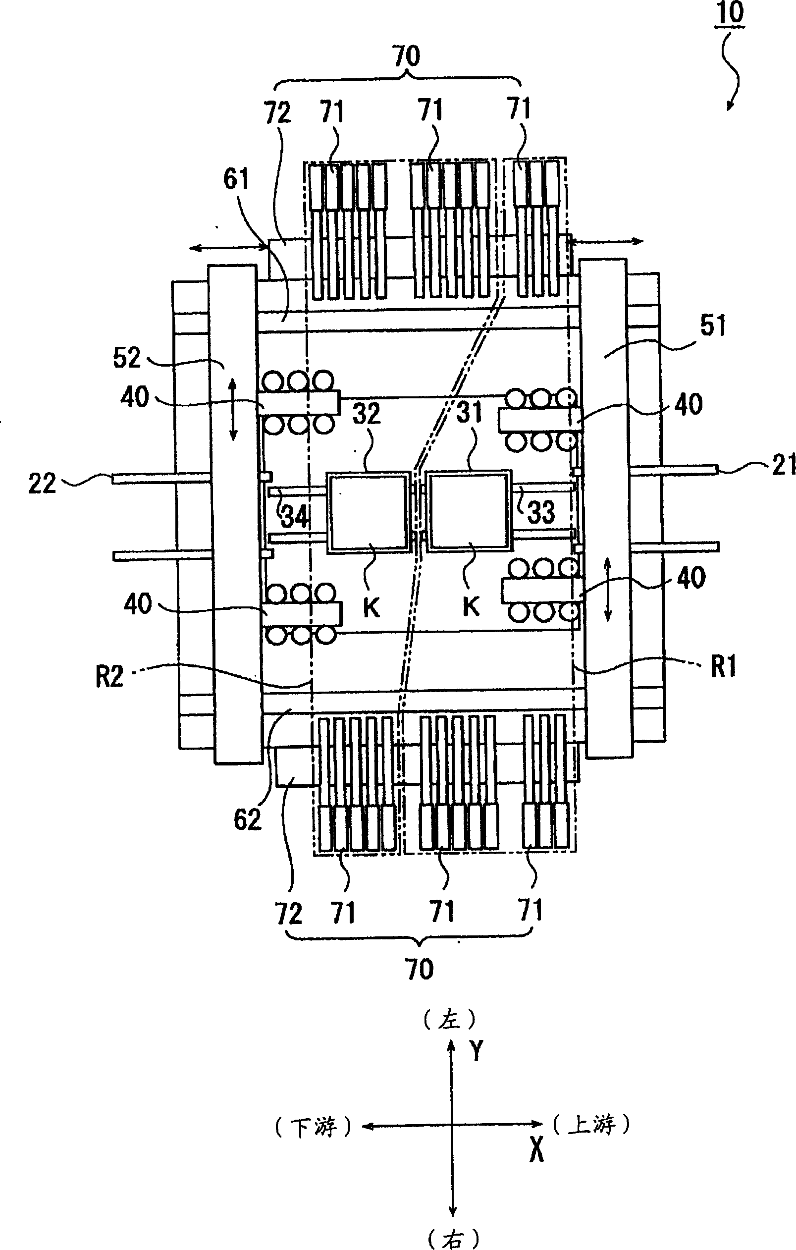
[0037] Below, according to Figure 1 to Figure 5 The electronic component mounting apparatus 10 according to the embodiment of the present invention will be described. figure 1 is a perspective view of the electronic component mounting apparatus 10, figure 2 Indicates a top view.

[0038] In addition, the electronic component mounting apparatus 10 is an apparatus that transports the board K in the transport direction, fixes it at a predetermined position on the board transport path, and mounts electronic components on the board K.

[0039] In the following description, the conveying direction of the substrate K is defined as the X-axis direction, and the direction approximately perpendicular to the conveying direction of the substrate K is defined as the Y-axis direction (see Figure 1 to Figure 5 ).

[0040] Electronic component mounting device 10 such as figure 1 and figure 2 As shown, it has: a rectangular frame-shape...


PUM


Abstract

he objective of the invention is to provide an apparatus for mounting electronic components capable of improving efficiency in mounting work to a substrate. The electronic component mounting device is provided with substrate-holding means 31 and 32 in the middle of the transfer path by transfer means 21 and 22 of a substrate K, a first positioning mechanism that positions the head along the guide frame with the aid of head guide frames 51 and 52 arranged over the transfer path, and a second positioning mechanism that positions the head along the transfer direction. Each head 40 is arranged at the mutually opposite surface side of each guide frame. The heads held by one guide frame and the heads held by the other guide frame perform mounting operation only to the mutually different substrates held by the substrate-holding means.

Description

technical field [0001] The present invention relates to an electronic component mounting device for positioning and mounting electronic components at predetermined positions with respect to a substrate. Background technique [0002] [Patent Document 1] JP-A-2003-243894 [0003] In the conventional electronic component mounting apparatus, there are: a substrate conveying unit that conveys the substrate in a predetermined direction; a substrate holding unit that is installed in the middle of the substrate conveying path; Orientation settings. In addition, it also has: a head unit for sucking the substrate conveyed along each guide frame; a guide moving mechanism for moving the guide frame along the substrate conveying direction; An electronic component supply unit of an electronic component (for example, refer to Patent Document 1). [0004] Moreover, each of the above-mentioned electronic component supply units is composed of a plurality of electronic component feeding dev...

Claims


Application Information

Patent Timeline
Patent Type & Authority Applications(China)
IPC IPC(8): H05K13/04H05K13/08
Inventor 黑田洁
Owner JUKI CORP
Why Eureka
Try Eureka