

Magneto rotor magnetizing and detecting apparatus
A detection device and magneto technology, applied in electromechanical devices, motor generator testing, manufacturing motor generators, etc., can solve problems such as uncertain power generation performance and energy waste, and achieve the effect of reducing working hours and eliminating energy waste
- Summary
- Abstract
- Description
- Claims
- Application Information
AI Technical Summary
Problems solved by technology
Method used
Image

Examples
Embodiment 1
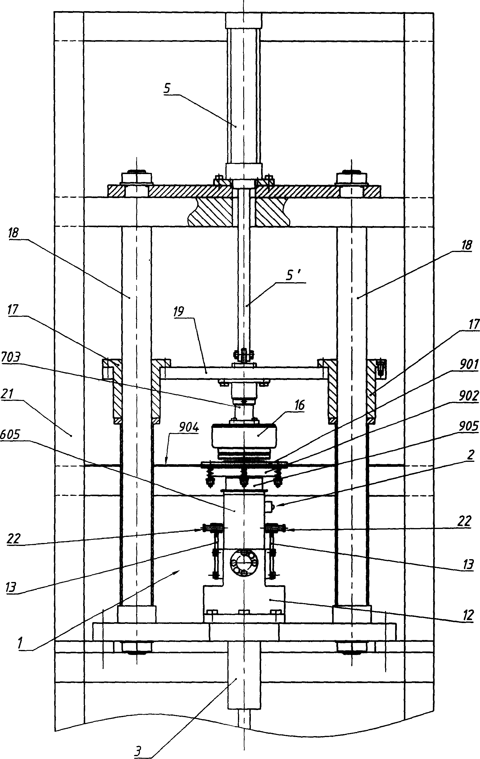
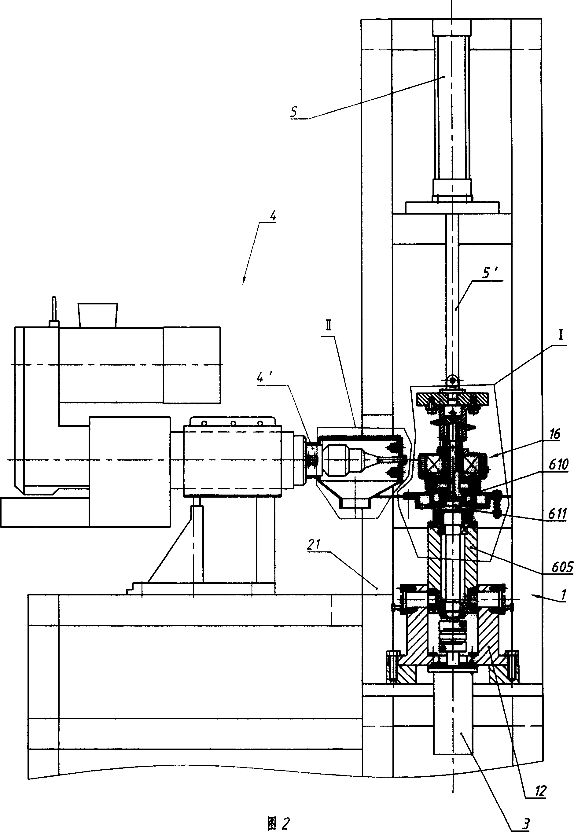
[0022] (see figure 1, 2, 4) What is said in the content of the invention, for example, is the fusion of the structural scheme in the "general description" and the existing balance detection and correction device, so the same parts as the "general description" will not be described in detail, and the fusion The part is: the propelling mechanism is the coaxial propelling cylinder 5 of its piston rod 5 ' and central axis 601 installed on the frame 21. The driving motor is a driving motor of a semi-balancing machine 1 installed on the frame 21 and combined with a computer to detect balance, and the central axis 601 is also the central axis 601 of the balancing machine 1 . The magneto rotor 16 is installed on the central shaft 601 through a positioning sleeve 602 coaxial with it, and the positioning sleeve 602 is set on the central shaft 601 in a clearance fit (the mating surfaces of the two have been finely ground in advance, and their fit Accuracy is IT4~IT6). The rear end of t...
Embodiment 2
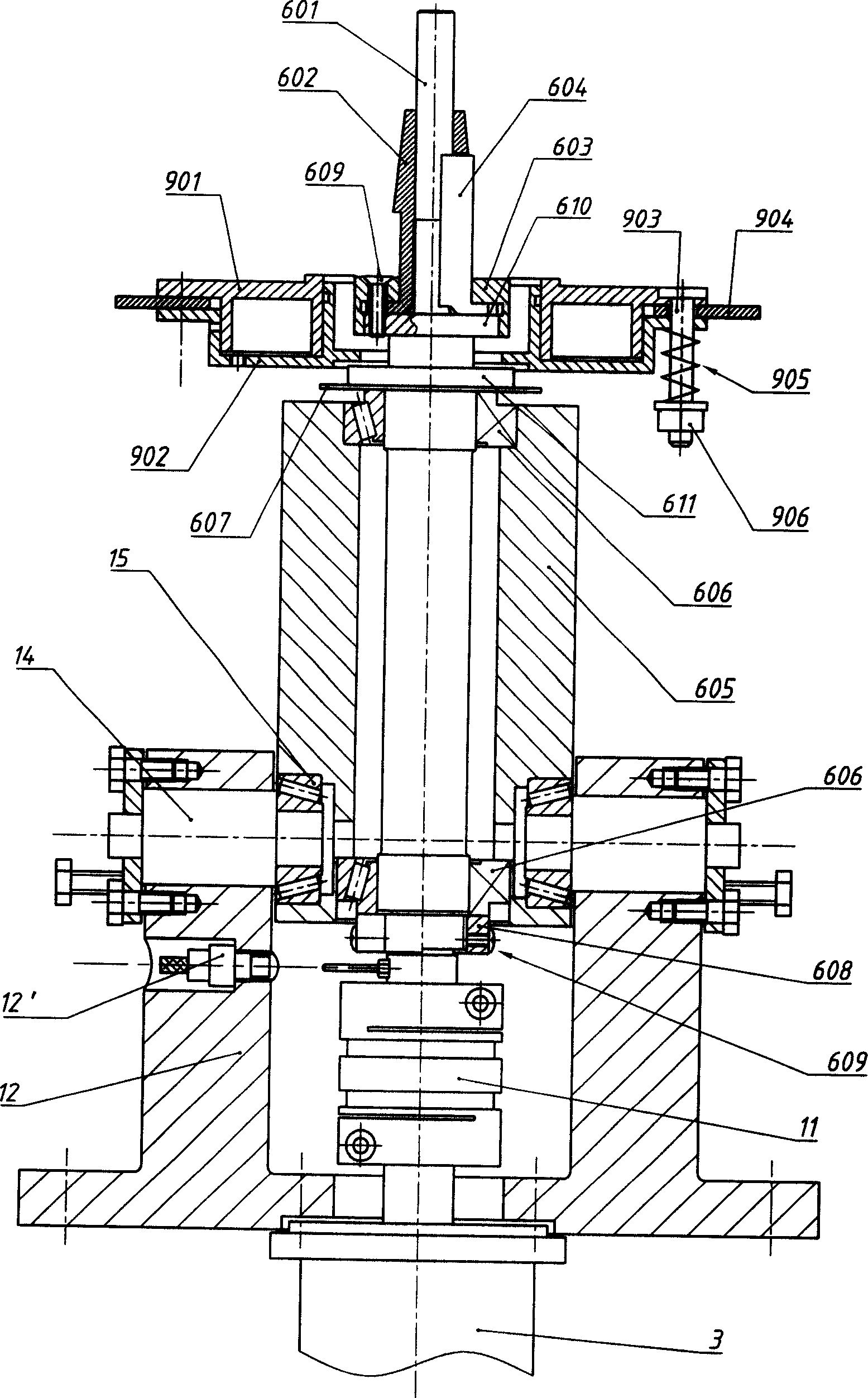
[0024] The existing balance detection and correction device integrated in Embodiment 1 includes a device that can only realize the combined functions of balance detection and balance correction with more than four power heads. This example is an improvement on the basis of Example 1, so only the different parts are still disclosed. The main difference is that the balancing machine 1 used in this example is a single-sided centrifugal vertical dynamic balancing machine (see image 3 ). The balancing machine 1 includes a base 12 installed on the frame 21 and a balancing machine central axle box 605 installed in the base 12 . The central axle box 605 is installed in the base 12 by a pair of swing bearing pins 14 symmetrically crossing the shell of the base 12, between the swing bearing pins 14 and the central axle box 605 by a radial thrust bearing 15 connect. The common axis of the two swing bearing pins 14 and the centripetal thrust bearing 15 thereof is on the same plane as ...
Embodiment 3
[0026] There is only one difference between this example and Embodiment 2, and the similarities will not be repeated. The different parts are: the coil connection sleeve 703 is pressed on the inner end face of the positioning pressing head 701 by a spring 705 (see Figure 5 ). There is a flange at the inner end of the positioning compression head 701, and a thrust bearing 706 is installed on the end face of the flange, and a spring guide post 704 and a spring guide post 704 are pressed on the other end face of the thrust bearing 706. Cover the spring 705 on the spring guide post 704, and the two ends of the spring 705 are respectively against the bottom of the inner hole of the coil connection sleeve 703 and the spring seat surface of the spring guide post 704 (in this example, the inner hole is Due to the size, it extends through the bearing connecting plate 19, and its bottom is the lower end surface of the cylinder connecting plate 20); between the part of the coil connect...
PUM
 Abstract
Description
Claims
Application Information