Fuel cell separator and method of manufacturing the separator

A technology for fuel cells and separators, applied in the direction of fuel cells, fuel cell components, solid electrolyte fuel cells, etc., which can solve the problems of hindering the improvement of productivity, difficulty in covering the sealing member 115, and the decline in the yield of manufacturing separators, etc. problem, to achieve the effect of increasing production, restraining cost increase and reducing cost

Inactive Publication Date: 2005-09-07
HONDA MOTOR CO LTD
View PDF1 Cites 8 Cited by
  • Summary
  • Abstract
  • Description
  • Claims
  • Application Information

AI Technical Summary

Problems solved by technology

[0014] Even if the precision of the equipment is improved, it is difficult to ensure that the entire surface of the gas passage and the product water passage of the peripheral portion 113a are covered by the sealing member 115, and it is likely that the yield of manufacturing the separator will decrease and hinder the improvement of the productivity.

Method used


Image

  • Fuel cell separator and method of manufacturing the separator
  • Fuel cell separator and method of manufacturing the separator
  • Fuel cell separator and method of manufacturing the separator

Examples


Embodiment Construction

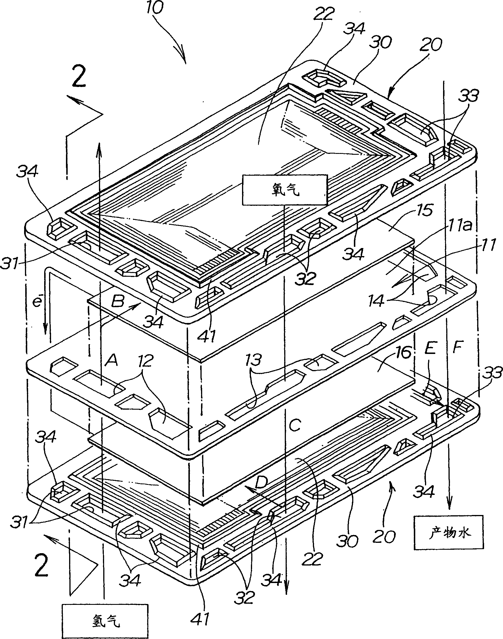
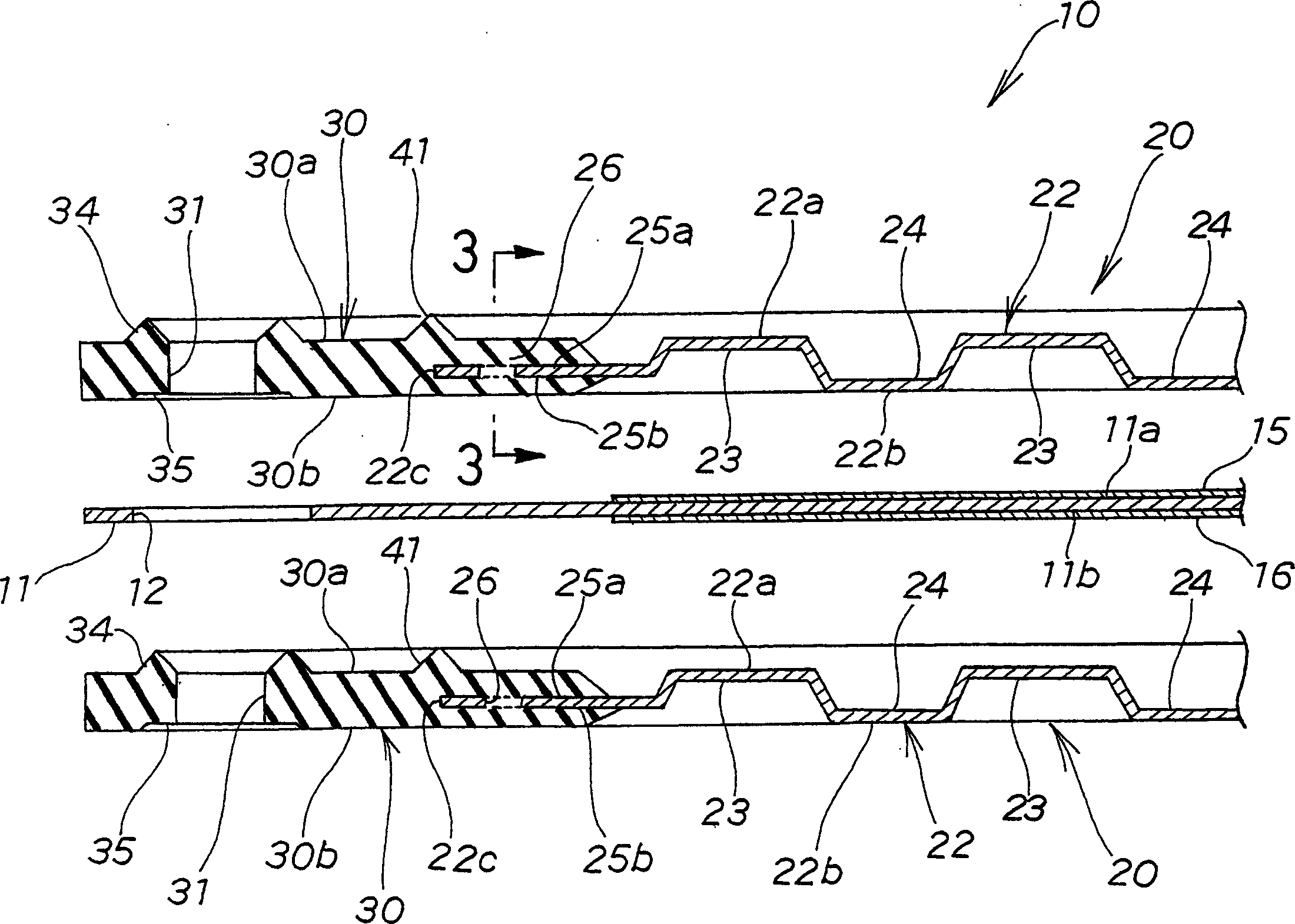
[0033] figure 1 The fuel cell 10 shown has the following structure: On the side of the upper surface 11a of the electrolyte membrane 11 and the lower surface 11b (see figure 2 ) sides are respectively arranged with a negative electrode 15 and a positive electrode 16, and an upper side separator 20 (fuel cell separator) is stacked on the negative electrode 15, and a lower side separator 20 is stacked on the positive electrode 16.

[0034] Here, the fuel cell 10 stacked by the electrolyte membrane 11, the negative electrode 15, the positive electrode 16, the upper separator 20, and the lower separator 20 is generally called a battery cell, and a plurality of stacked battery cells is called a fuel cell. In this specification, for ease of understanding, the battery unit is referred to as a fuel cell.

[0035] At the outer peripheral portion of the electrolyte membrane 11, there are a plurality of hydrogen gas passages (gas passages) 12 for introducing hydrogen gas (reaction gas)...


PUM


Abstract

A fuel cell separator ( 20 ) having a central part ( 22 ) and an outer peripheral part ( 30 ). The central part is a metal member made of stainless steel or the like. Multiple gas passages ( 31, 32 ) and multiple product water passages ( 33 ) are formed in the peripheral part. To ensure corrosion resistance of the gas passages and the product water passages, the peripheral part is a rubber member made of silicone rubber. A projecting central seal part ( 41 ) for surrounding the central part is formed integrally with the peripheral part.

Description

technical field [0001] The present invention relates to a fuel cell separator provided in its peripheral portion with a plurality of passages for guiding reaction gas and reaction products and a manufacturing method thereof. Background technique [0002] Figure 6 shows a prior art fuel cell. This fuel cell 100 is manufactured by arranging the negative electrode 102 and the positive electrode 103 on the upper surface side and the lower surface side of the electrolyte membrane 101, respectively; Near the periphery of the membrane 101 and the periphery of the upper separator 105; and the separator 105 is arranged on the lower side of the positive electrode 103, and the lower gasket 106 is sandwiched between the periphery of the electrolyte membrane 101 and the periphery of the lower separator 105 nearby. [0003] With this fuel cell 100 , hydrogen gas is supplied through a plurality of hydrogen gas passages 107 as indicated by arrow a. The hydrogen gas in the hydrogen gas ch...

Claims


Application Information

Patent Timeline
Patent Type & Authority Applications(China)
IPC IPC(8): H01M8/02B29C45/14H01M2/08H01M8/10
CPCH01M8/0271H01M8/0282Y02E60/50H01M8/0254H01M8/0206Y02P70/50H01M8/02
Inventor 河内慎弥木村实基彦
Owner HONDA MOTOR CO LTD
Why Eureka
Try Eureka