
Skirt guided globe valve

A valve plug and valve stem technology, applied in the field of skirt-guided spherical valves, can solve problems such as hydrodynamic resistance and maximum flow drop

Inactive Publication Date: 2005-09-14
FISHER CONTROLS INT LLC
View PDF1 Cites 9 Cited by
  • Summary
  • Abstract
  • Description
  • Claims
  • Application Information

AI Technical Summary

Problems solved by technology

In addition to reducing the maximum flow rate by reducing the diameter of the flow path, the obstruction of the skirt also creates eddies, turbulence and pressure gradients in the flowing fluid, resulting in hydrodynamic resistance.

Method used


Image

  • Skirt guided globe valve
  • Skirt guided globe valve
  • Skirt guided globe valve

Examples


Embodiment Construction

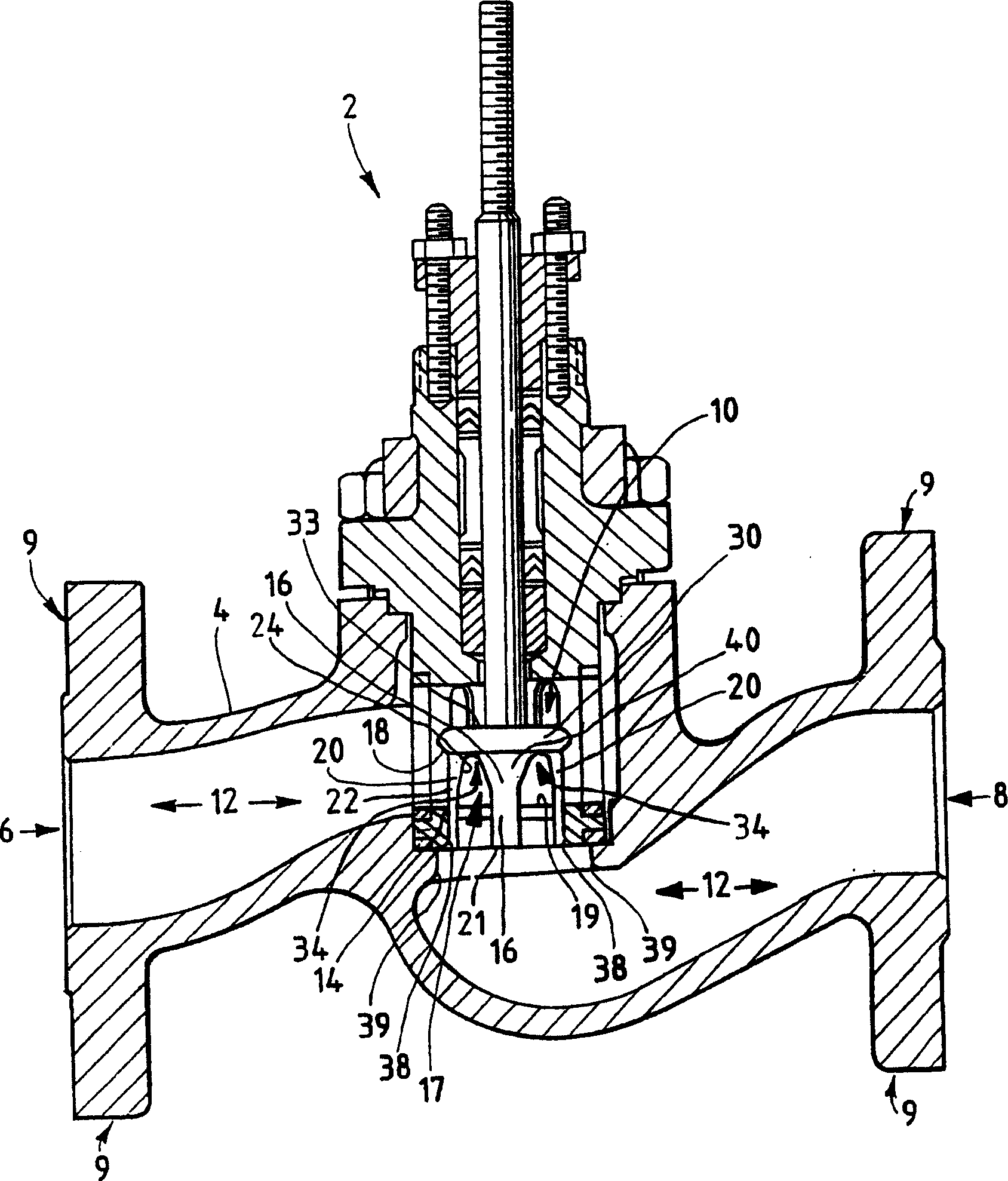
[0016] Skirt guided ball valves have been used in the process control industry for decades. While skirt pilot valves have many advantages, they also have serious drawbacks. One drawback is the reduced flow compared to other types of valves because in skirt pilot valves a portion of the plug can never be fully retracted off the seat. The two-way skirt-guided ball valve disclosed herein has increased flow as a result of surface topography and mixing edges in the valve to achieve a streamlined, laminar flow while maintaining the same Pilot valves are usually associated with efficiency and reliability.

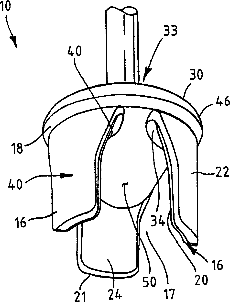
[0017] figure 1 A skirt piloted ball valve 2 is shown having a valve body 4, an outlet 6, an inlet 8 (when used in an up-flow configuration) and a skirt plug 10 (in figure 2 in more detail). The outlet 6 and the inlet 8 generally have a mounting mechanism such as a flange 9 to install the ball valve 2 into the process system. The outlet 6 and the inlet 8 are connected by a f...


PUM


Abstract

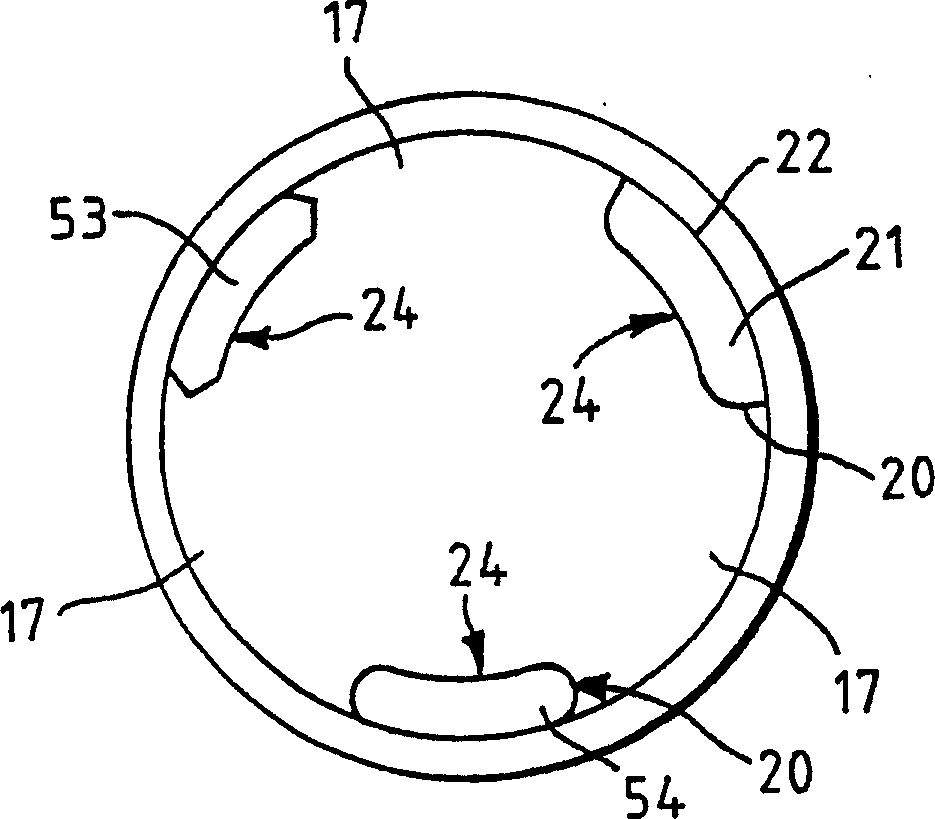
A skirt guided control valve (2) provides streamlined flow and minimum resistance to flow in flow up and flow down conditions when the valve is open. The skirt guided control valve has a fluid inlet (8), a fluid outlet (6), a passageway (12) disposed between the fluid inlet and fluid outlet, a valve seat (14) and a valve plug (10) with a skirt (16). The valve seat and the skirt portion of the valve plug include blended edges (38) and contoured surfaces (22) to provide for streamlined flow.

Description

technical field [0001] This invention relates generally to control valves, and more particularly to skirt guided ball valves with increased flow. Background technique [0002] Power plants and manufacturing plants use process control devices to control the flow of fluids in the process, where "fluid" includes liquids, gases or any mixture that can flow through pipelines. Manufacturing processes that produce consumer goods or goods such as fuel, food, and cloth require control valves to control and regulate fluid flow. Even a medium-sized plant may use hundreds of control valves to control process procedures. Control valves have been in use for more than a century, during which time valve designers have continually improved the operating characteristics of control valves. [0003] When designing a process program, the designer is faced with many design requirements and design constraints. While the valve must be able to provide the required flow when the valve is in the fu...

Claims


Application Information

Patent Timeline
Patent Type & Authority Applications(China)
IPC IPC(8): F16K1/52F16K1/54F16K3/24F16K47/04
CPCY10T137/86799F16K1/52Y10T137/86759F16K1/54F16K47/04
Inventor 威廉·E·韦尔斯戴维·G·哈尔姆
Owner FISHER CONTROLS INT LLC
Learn More