Diagonal fan having an optimized housing

A diagonal flow fan and diagonal flow technology, which is applied to liquid fuel engines, components of pumping devices for elastic fluids, axial flow pumps, etc., to achieve the effect of reducing torque and small torque requirements

Active Publication Date: 2021-05-25
EBM PAPST MULFINGEN GMBH & CO KG
View PDF7 Cites 0 Cited by
  • Summary
  • Abstract
  • Description
  • Claims
  • Application Information

AI Technical Summary

Problems solved by technology

The problem in this case is that the running wheel is driven by an electric motor, especially by an asynchronous motor, since the motor can only be optimally coordinated with one variant

Method used


Image

  • Diagonal fan having an optimized housing
  • Diagonal fan having an optimized housing
  • Diagonal fan having an optimized housing

Examples


Embodiment Construction

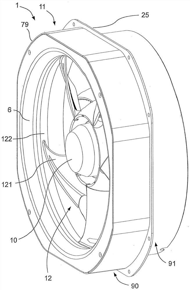
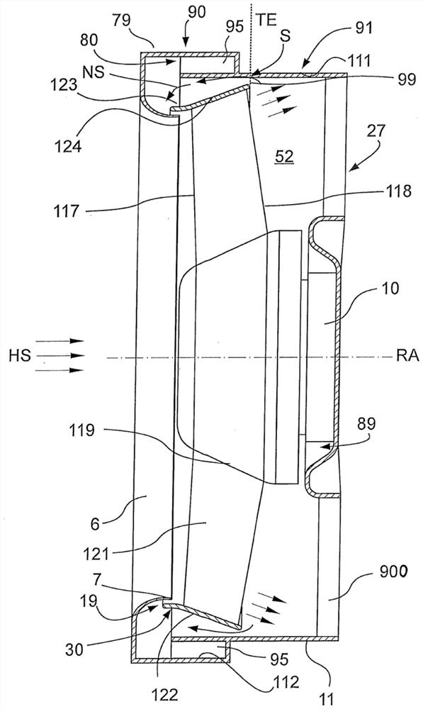
[0028] according to figure 1 with figure 2 The diagonal flow fan 1 comprises a housing 11 in which an electric motor 10 configured as an outer rotor motor is accommodated and is connected to a diagonal flow impeller 12 in order to rotate the latter about an axis of rotation RA during operation. Diagonal flow impeller 12 is fixed on electric motor 10 with its hub 119 . A plurality of rotor blades 121 distributed in the circumferential direction extend radially outward from the hub 119 , and the rotor blades are closed at their radially outer ends by an oil flinger 122 . The impeller blade 121 has a blade front edge 117 and a blade rear edge 118, viewed from the radially inner side to the radially outer side, their distribution is inclined towards the inlet side of the diagonal flow fan 1 relative to the vertical line of the rotation axis , wherein the angle at the rear edge 118 of the blade is greater than the angle at the front edge 117 of the blade.

[0029] On the suctio...


PUM


Abstract

The invention relates to a diagonal fan (1), comprising an electric motor (10), a housing (11), and a diagonal impeller (12), which is accommodated in the housing (11) and can be powered via the electric motor (10), the diagonal flow of which generated during operation is diverted to a axial flow direction. The impeller (12) has impeller blades (121) distributed in the circumferential direction, and has an air inlet and an air outlet. The housing forms a flow channel for an airflow generated by the impeller, which has an axial portion that is not rotation-symmetrical, and a cylindrical axial portion, which, as viewed in the flow direction, axially directly adjoins the same. An air outlet-side radially outer end of the impeller is arranged in the cylindrical axial portion of the flow channel of the housing, and an air gap is provided between the radially outer end and the housing. The axial portion of the impeller that is not rotation-symmetrical is arranged in a region of the flow channel that is adjacent to the air inlet side of the air gap in an axial plane with the impeller such that the axial portion that is not rotation-symmetrical encloses the impeller, at least sectionally.

Description

technical field [0001] The invention relates to a diagonal flow fan with a housing optimized with regard to the torque of the electric motor used for the drive. Background technique [0002] Diagonal flow fans and their use are generally known from the prior art, for example from DE 10 2014 210 373 A1. [0003] Diagonal flow fans are used in applications with high demands on air power at high back pressure and low usable space, for example in cooling technology or in smoke extraction systems. Due to the large motor diameter of the axially centrically arranged motor and the radial widening of the hub in oblique flow fans compared to the installation space, the exhaust surface at the exhaust opening is relatively small, so that during the flow due to the Diagonal flow fans have high dynamic pressures at the outlet resulting in high discharge losses. [0004] When installing the oblique flow fan in a cylindrical housing, the torque requirement of the fan is reduced compared t...

Claims


Application Information

Patent Timeline
Patent Type & Authority Applications(China)
IPC IPC(8): F04D17/06F04D19/00F04D27/00F04D29/42F04D29/54F04D29/32
CPCF04D19/002F04D29/326F04D29/545F04D29/4226F04D27/009F04D17/06F04D25/06F04D29/325
Inventor O·哈弗D·格伯特
Owner EBM PAPST MULFINGEN GMBH & CO KG
Why Eureka
Try Eureka