Controllable guided air supply system for drying houses

A technology of air supply system and drying room, which is applied in the direction of drying gas arrangement, drying, drying machine, etc. It can solve the problems of prolonging the drying cycle, increasing the pressure head of the fan, and increasing the power consumption, so as to improve the drying efficiency and improve the drying efficiency. The effect of air supply flow rate and reduction of air supply resistance

Inactive Publication Date: 2005-09-21
SHANGHAI UNIV OF ENG SCI
View PDF0 Cites 8 Cited by
  • Summary
  • Abstract
  • Description
  • Claims
  • Application Information

AI Technical Summary

Problems solved by technology

Although this method can achieve the purpose of drying, it has the following defects: 1. The airflow generated by the circulating fan is injected into the air supply ceiling without restriction, and the airflow diffuses rapidly and the streamline is disordered, especially at the air outlet of the air supply ceiling. The air flow is partially blocked, the pressure loss is large, the pressure head of the fan must be increased, resulting in increased power consumption, and aluminum transverse partitions are still needed between several fans9
2. It is necessary to build a supply and return air ceiling with a size similar to the bottom area of ​​the drying room and a net height of about 1.5 meters. Due to the needs of installation and maintenance, the ceiling should be able to accommodate people, so the initial investment is large and the space occupied is large.
3. The head-on wind speed along the height of the material to be dried cannot be adjusted, resulting in uneven distribution of the vertical head-on wind speed, so that the material cannot be dried evenly, which not only prolongs the drying cycle, but also has a negative impact on the drying quality and drying cost

Method used


Image

  • Controllable guided air supply system for drying houses
  • Controllable guided air supply system for drying houses
  • Controllable guided air supply system for drying houses

Examples


Embodiment Construction

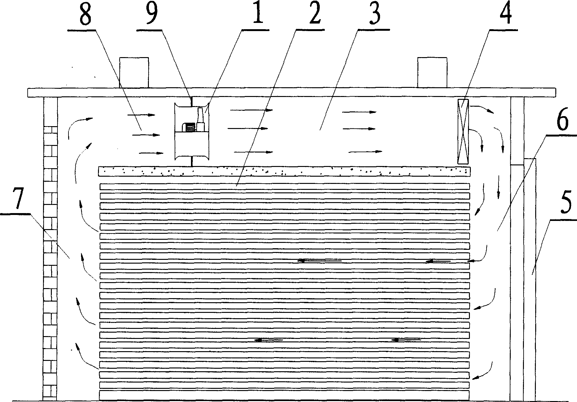
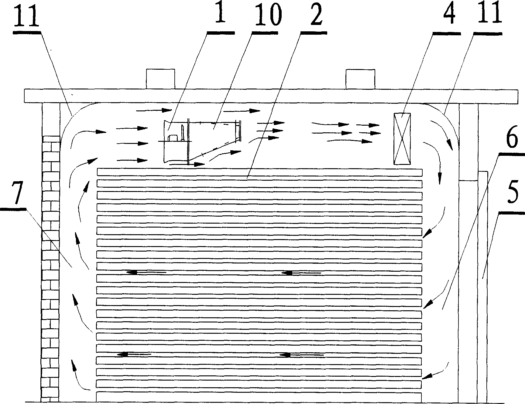
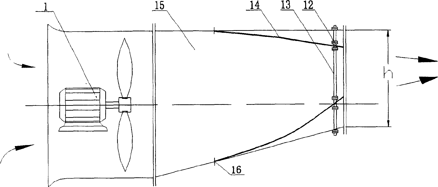
[0013] Depend on Figure 2-Figure 4 As shown, a controllable guided air supply system for a hot air drying room, which includes a fan, is characterized in that a guided air supply device 10 is placed at the air outlet of the fan 1, and the guided air supply device has a round-to-rectangular shape The variable-diameter housing 15 is equipped with 1 or 2 adjustable guide tongues 14, and a guide bend 11 is disposed at the corner of the side wall on the top of the drying room, which cooperates with the guide air blower 10 to form a smooth and controllable flow. Attach airflow. The guide air blower is installed at the air outlet of the high-efficiency environmental protection fan, and is connected with the fan casing by bolts. The shell of the guide air blower is a round-to-rectangular special-shaped variable-diameter shell. The connection between it and the fan is circular, and the air outlet is rectangle.

[0014] Depend on image 3 , Figure 4 As shown, the adjustable deflec...


PUM


Abstract

This invention discloses an adjustable guide air supply system of drying chamber. Its feature is that guider air supplier is fixed at uptake of fan, specific change size shell of circle to rectangle is on the supplier, and adjustable diversion hyoplastron is fixed in it. Diversion bent plate is set lateral wall nook of drying chamber top part, smooth and fluent controlled additional air current is formed by it coordinated with guide sir supplier. The utility effect is that the adjustable diversion hyoplastron can adjust velocity, direction and flux of the drying air current to make it accordance with request of drying technique, so drying quality is improved. Smooth and fluent controlled additional air current is formed by diversion bent plate coordinated with guide sir supplier to reduce air supply resistance, improve air supply quality, shorten drying period and improve efficiency. Air supply suspended ceiling, air return suspended ceiling and aluminum separator between fans in existing drying chamber can be removed, so it can decrease the chamber height, saving initial cost. High efficiency environmental protection type fan is used in this invention, so noise pollution can be reduced, electricity consumption can be reduced, and dry cost also can be reduced.

Description

technical field [0001] The invention relates to the field of hot air drying of materials such as wood, food, medicine, agricultural and sideline products, and chemical products, and is suitable for the adjustable and guided air supply system of various hot air drying rooms, drying tunnels and ovens. Background technique [0002] The drying process is the most energy-intensive but indispensable link in the processing industries of wood, medicine, food, chemical products, agricultural and sideline products, etc. The hot air drying room is an important equipment for drying operations, and the hot air circulation system in the drying room is to improve drying efficiency. The key to building efficiency, saving energy, and ensuring product quality. According to the technical requirements of drying different materials, there must be an air flow in the drying room that can be set as required and whose temperature and humidity can be adjusted to flow on the surface of the material to...

Claims


Application Information

Patent Timeline
Patent Type & Authority Applications(China)
IPC IPC(8): F26B21/02F26B21/12
Inventor 曹伟武严平钱尚源
Owner SHANGHAI UNIV OF ENG SCI
Why Eureka
Try Eureka