
Tensile-shear compressive-shear complex loading tester

A test device and composite loading technology, applied in the direction of measuring device, machine/structural component testing, instruments, etc., can solve the problems of high manufacturing cost, high equipment price, and high test cost, and achieve low manufacturing cost, compact structure, and easy use. handy effect

Inactive Publication Date: 2005-09-21
NANJING UNIV OF AERONAUTICS & ASTRONAUTICS
View PDF0 Cites 21 Cited by
  • Summary
  • Abstract
  • Description
  • Claims
  • Application Information

AI Technical Summary

Problems solved by technology

[0003] For a long time, it has been very difficult to realize combined loading of tension-shear and compression-shear for this type of member.
At present, it can be realized by multi-channel coordinated loading system or multi-axis testing machine and auxiliary fixtures, but due to the high price of these equipment and the difficulty in the realization process, it is rarely used
[0004] Another method is to realize the tension-shear and compression-shear test of the plate through bending and torsion through the box section composed of the plate and ribs, but this method is suitable for the stability test of the plate, and the test cost is relatively high in the strength test , and cannot achieve satisfactory results
[0005] The current composite compression-shear loading device can only realize the composite stress test of compression and shear, but cannot realize the composite stress test of tension and shear, and the test effect is not good, especially for small-sized specimens
Also not suitable for strength tests
At the same time, if the ratio of pressing and shearing changes, the fixture needs to be replaced, which requires high installation technology, inconvenient use, and high manufacturing cost.
[0006] It is very difficult to realize tensile shear and compressive shear tests of different proportions at the same time on the same test device using the above methods

Method used


Image

  • Tensile-shear compressive-shear complex loading tester
  • Tensile-shear compressive-shear complex loading tester
  • Tensile-shear compressive-shear complex loading tester

Examples


Embodiment Construction

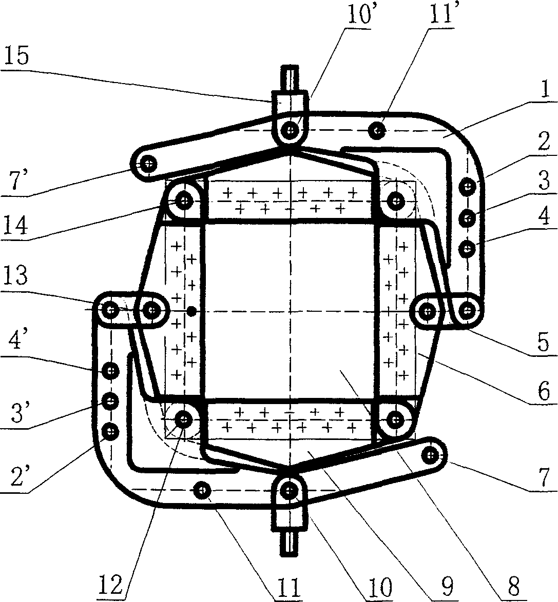
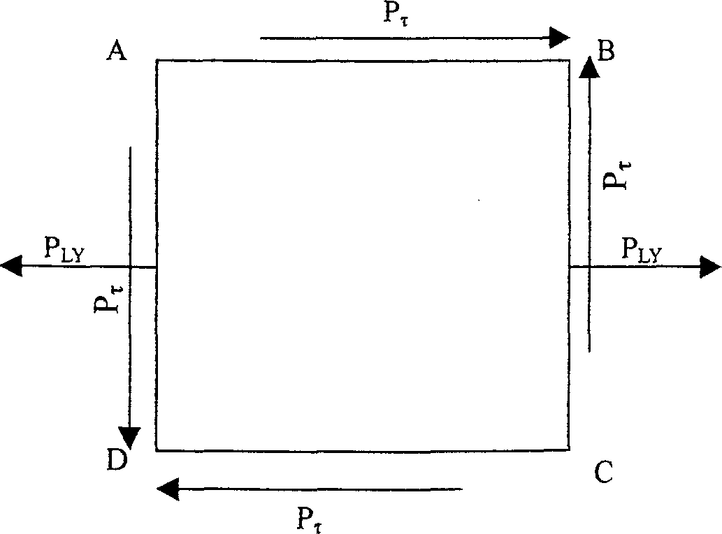
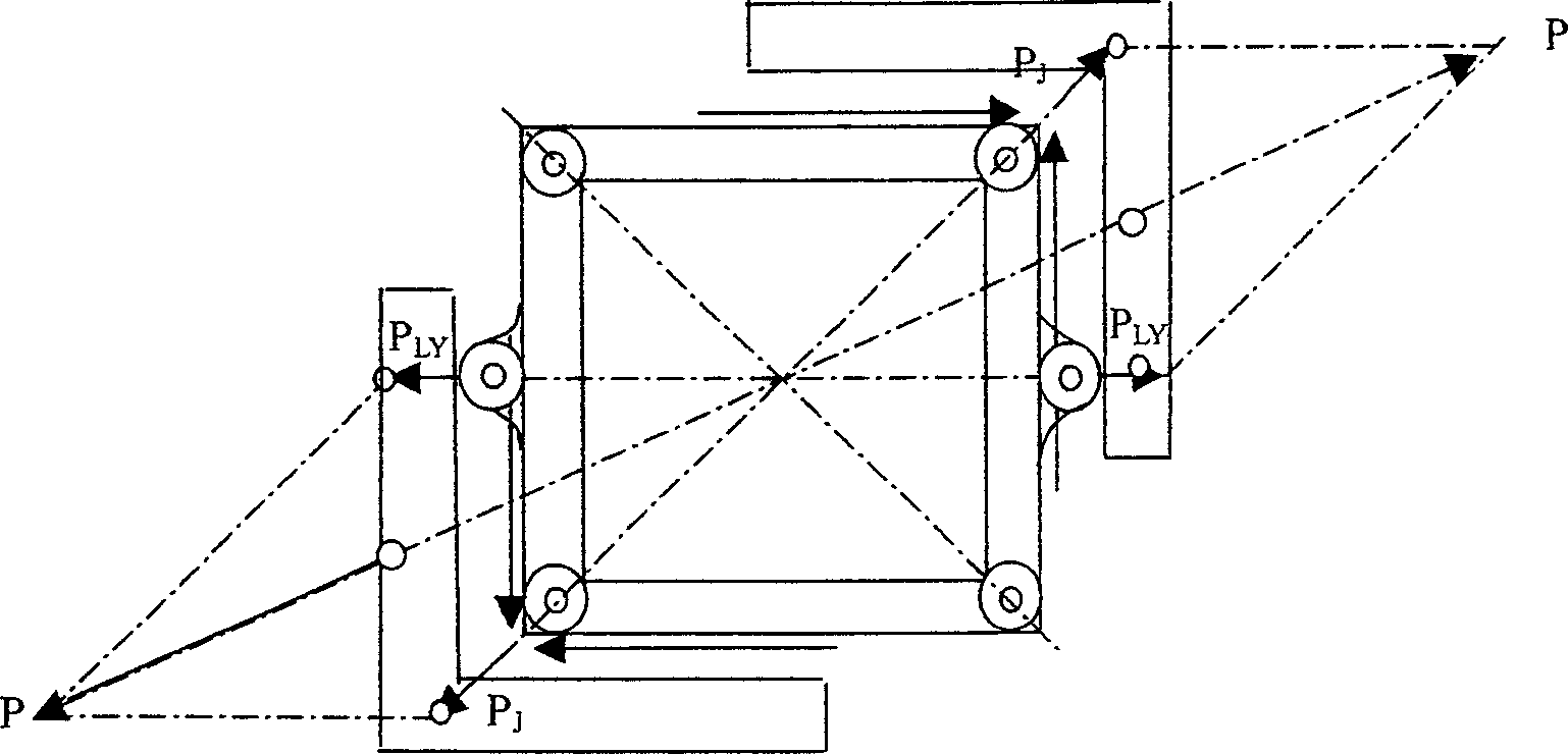
[0025] It can be seen from the figure that the tensile-shear-compression-shear multiple loading test device is composed of four shear and tension-compression loading splints 6 and 9 connected to form a rectangular loading frame, and two L-shaped levers 1 are symmetrically placed on one outside of the rectangular loading frame. On the diagonal, that is, the ends of the short longitudinal rods of the L-shaped lever 1 are respectively connected to the midpoints of the two shearing and tension-compression loading splints 6 on the two opposite sides through hinged connecting pieces 5, and the horizontal long rods of the L-shaped lever 1 The midpoint of the middle point is connected to the midpoints of the other two shearing and tension-compression loading splints 9 of the other two opposite sides by hinged lugs 15 respectively. When a single axial tensile force is applied to the pair of hinged lugs 15, the test device can be automatically centered under load. The two longitudinal b...


PUM


Abstract

This invention relates to one pulling and pressing shearing test device and structure force test device, which comprises the following parts: four pieces of shearing and pulling and pressing loading boards; one rectangle loading frame; two L-shape lever symmetrically hinged with each other and fixed on the rectangle loading frame one catercorner, wherein the L-shape lever is separately loaded with pulling and pressing holes. The test device can realize the compound test on the same one test device of general test machine.

Description

technical field [0001] The tension-shear-compression-shear composite loading test device of the invention belongs to the field of structural experiment mechanics. Background technique [0002] In aeronautical, aerospace, and marine engineering structures, flat plates and stiffened plates are typical stressed members, and they are all in a state of unidirectional tension, compression and shearing. Stability and strength under stress are important research topics in structural mechanics. Especially in the design of modern aircraft, it is necessary to study the strength of thin-walled structures such as skins under complex loads. It is urgent to realize this load state in the laboratory to assess the strength of materials and prepare for the next step of theoretical establishment. . [0003] For a long time, it has been very difficult to realize combined loading of tension-shear and compression-shear for this type of member. At present, it can be realized by multi-channel co...

Claims


Application Information

Patent Timeline
IPC IPC(8): G01M99/00G01N3/00
Inventor 汪勇汤剑飞黄晶林智育
Owner NANJING UNIV OF AERONAUTICS & ASTRONAUTICS
Learn More