Parts mounting apparatus

A technology for installing devices and components, applied in the direction of assembly machines, electrical components, electrical components, etc., can solve the problem of inability to solve the problem of component installation space 2 garbage, etc., and achieve the effect of improving the use efficiency

Active Publication Date: 2005-09-28
JUKI AUTOMATION SYST
View PDF0 Cites 5 Cited by
  • Summary
  • Abstract
  • Description
  • Claims
  • Application Information

AI Technical Summary

Problems solved by technology

[0011] However, any form of the component mounting device of the above-mentioned prior art cannot solve the garbage in the component mounting space 2. Because the air pressure inside and outside the component mounting space 2 is the same, the floating dust outside the mounting space 2 is easy to flow from the component supply opening 14, Components such as the substrate delivery opening 12 and the substrate delivery opening (not shown) enter the interior of the component mounting space 2

Method used


Image

  • Parts mounting apparatus
  • Parts mounting apparatus
  • Parts mounting apparatus

Examples


Embodiment

[0039] A component mounting apparatus according to an embodiment of the present invention will be described below with reference to the drawings.

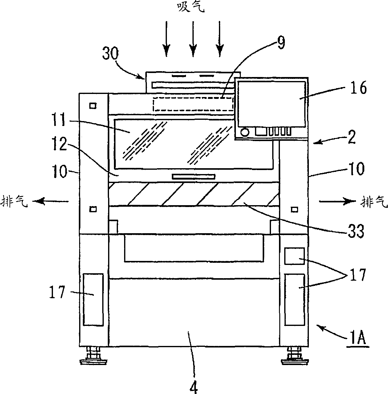
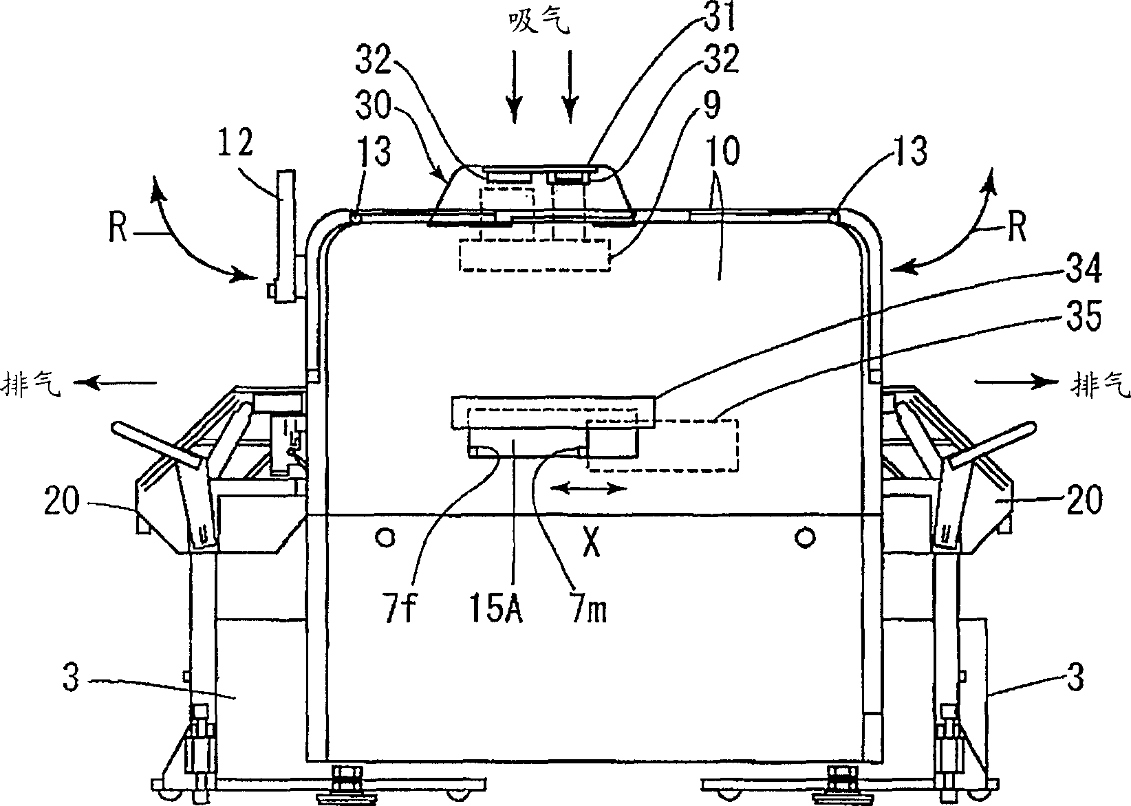
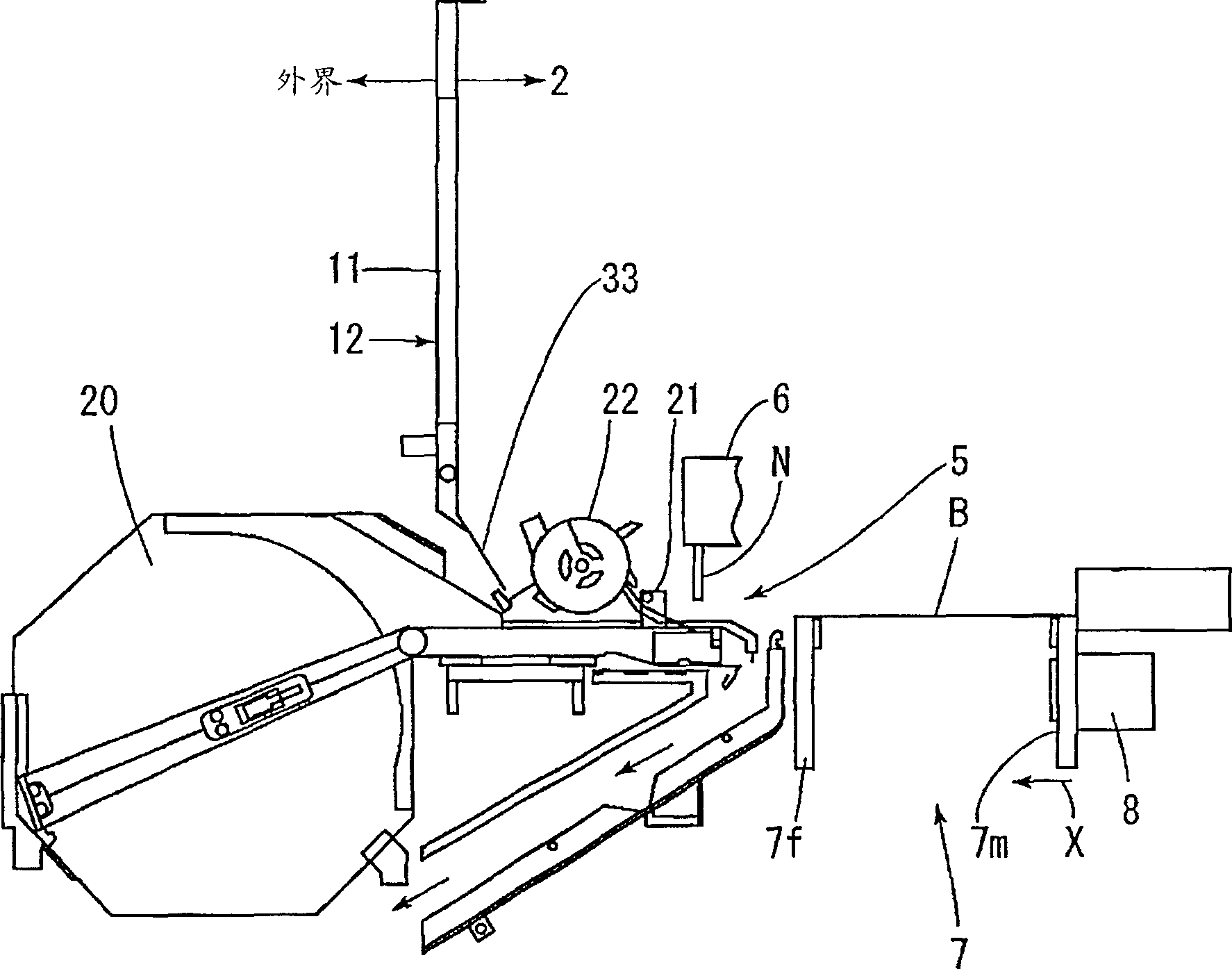
[0040] FIG. 1 is an external view of a component mounting device according to a first embodiment of the present invention, Figure 1A is its front view, Figure 1B is its side view. figure 2 It is a partial sectional view of the component supply opening part of the component mounting apparatus of this invention. image 3 It is a schematic plan view showing the positional relationship of the circuit boards on the board transfer unit.

[0041] In addition, in the structure and structure of the component mounting apparatus of the present invention, the same components as those of the conventional component mounting apparatus 1B are given the same reference numerals, and the description of the structure and structure will be omitted.

[0042] In FIG. 1 , reference numeral 1A denotes a component mounting apparatus of an embodiment of ...


PUM


Abstract

To obtain a component-mounting method and a component-mounting apparatus, by which a component can be mounted on an electronic circuit substrate, while maintaining the inside of component-mounting space at a cleaning state. The component-mounting apparatus 1A is constituted so that the area of a component supply aperture part 14 in the component-mounting space 2 covered with a cover 10 is narrowed by a flap cover 33, a substrate carry-in aperture part 15A and a substrate carry-out aperture part 15B are also narrowed by a fixing plate 34 and a closing plate 35, as required, clean air is suckedfrom an upper air supply means 30, and in a state with the air pressure in the component-mounting space 2 being increased higher than the atmospheric pressure of outside air, a component from a component cassette 20 is carried to the surface of the electronic circuit substrate B through a substrate carrying conveyer 7.

Description

technical field [0001] The present invention relates to a component mounting device capable of greatly extending maintenance intervals. Background technique [0002] Existing component mounting devices are mainly large-scale high-speed component mounting devices called rotary machines. However, in recent years, due to the large size and high price of the rotary machine, it has fallen out of favor, and the small movable part attracting head type part mounting device is becoming the mainstream. [0003] FIG. 4 shows the appearance of a conventional component mounting device. Figure 4A is its front view, Figure 4B By Figure 4A The arrow marks the side view seen in direction B. Figure 5 It is a partial cross-sectional view of a component supply opening of a conventional component mounting device. [0004] in addition, Figure 4A omitted in Figure 4B Shown is a cart carrying a number of boxes of various components. [0005] In FIG. 4 , reference numeral 1B denotes a pri...

Claims


Application Information

Patent Timeline
Patent Type & Authority Applications(China)
IPC IPC(8): H05K13/04B23P21/00
Inventor 林详一木村明
Owner JUKI AUTOMATION SYST
Why Eureka
Try Eureka