Construction machine

A technology for construction machinery and working machines, which is applied in sewing equipment, sewing machine components, earthmoving machines/shovels, etc., can solve the problems of design, manufacturing work burden, difficult flow of molding materials, and large number of parts, and achieves a reduction in the number of parts. Improved weight, load-resisting strength, and improved mechanical reliability

Inactive Publication Date: 2005-09-28
KOMATSU LTD +1
View PDF2 Cites 6 Cited by
  • Summary
  • Abstract
  • Description
  • Claims
  • Application Information

AI Technical Summary

Problems solved by technology

[0007] However, the above-mentioned rotating frame, as described in JP-A-2002-146834, has the advantage of suppressing weight increase by selecting steel plates with optimum thickness when it is manufactured from metal plates, but the number of parts is large, In addition, since the components are joined by welding, there is a problem that many man-hours are required for welding and the cost increases.
[0008] In addition, the cross-sectional view of the junction between the components, such as the components b1 and b2, is Figure 4B As shown, since they are assembled against each other, there is a problem that a sharp groove is formed at the junction, and stress concentration is likely to occur, making it difficult to ensure strength.
[0009] Therefore, in order to prevent the occurrence of stress concentration during movement, in order to form a smooth R portion at the joint during the joining work, in addition to the welding joint work, sealing work, grinding work, etc. are required, and design and manufacturing work are required. Unnecessary burden, resulting in increased workload
[0010] In addition, in the case of manufacturing the rotating frame by casting, although there is an advantage of having a degree of freedom in shape, the number of parts and the number of assembly man-hours are reduced, but in the case of forming a thin wall, there may be holes that make it difficult for the molding material to flow. Depending on the size of the part, it may also cool down before the molding material bypasses, resulting in poor yield
[0011] Therefore, in the case of castings, due to such manufacturing constraints, a predetermined thickness is required. For example, a thickness of 25 mm is required where a thickness of 10 mm is sufficient, and there is a problem of increasing weight.

Method used


Image

  • Construction machine
  • Construction machine
  • Construction machine

Examples


Embodiment Construction

[0030] Hereinafter, embodiments of the present invention will be described with reference to the drawings.

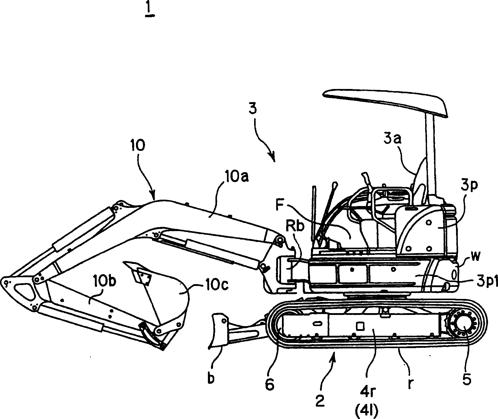
[0031] The hydraulic excavator (engineering machine) 1 of the embodiment of the present invention, as by side view figure 1 As shown in FIG. 1 , it includes an undercarriage 2 provided with crawler belts r for movement, and a revolving upper body 3 rotatably mounted on the upper part thereof for an operator to sit on and perform work.

[0032] The undercarriage 2 has drive wheels 5 and floating wheels 6 attached to both ends of the track frames 4 r and 41 , respectively, and the crawler belt r is wound between the driving wheels 5 and the floating wheels 6 .

[0033] Further, a dozer blade b used for backfilling soil excavated by the bucket 10c is swingably disposed on the front portion of the undercarriage 2 so as to perform a predetermined operation as a dozer blade.

[0034] A driver's seat 3a on which an operator sits and performs work is arranged on the upper par...


PUM


Abstract

A construction machine which comprises an undercarriage, an upper structure rotatably mounted on a top of the undercarriage, and a work equipment movably supported at a front of the upper structure, in which within a frame assembly that forms a base of the upper structure, at least following components are produced by casting a weldable material: a work equipment support that supports the work equipment, a right vertical rib and a left vertical rib, a distance therebetween widening gradually as they extend backwards from the work equipment support, a bottom plate that extends towards inside, adjoining bottom edges of the work equipment support, the right vertical rib and the left vertical rib.

Description

technical field [0001] The present invention relates to a construction machine, in particular to a frame assembly constituting a base of an upper rotating body of the construction machine. Background technique [0002] According to the bulletin No. 2002-146834, the backhoe excavator 100, as its Figure 5 As shown in the right side view, it is mainly composed of a lower traveling device 102, an upper rotating body 103, an excavating device 104 mounted on the rotating body 103, and the like. [0003] Such as Figure 6 As shown in the exploded view of the upper rotating body 103, the rotating frame F disposed on the bottom surface of the upper rotating body 103 is provided with a support body 111 that axially supports the excavating device 104 freely rotatable in the horizontal direction. [0004] With the above configuration, various loads are applied to the revolving frame F supporting the excavation device 104 by the operation of the excavation device 104 of the backhoe 100...

Claims


Application Information

Patent Timeline
Patent Type & Authority Applications(China)
IPC IPC(8): B62D21/18D05B65/00E02F9/08
CPCE02F9/0825E02F9/08B62D21/18
Inventor 高野善之清水贤一远藤武士木村泰治
Owner KOMATSU LTD
Why Eureka
Try Eureka