Low-power consumption electromechanical antitheft warning trick lock

A password anti-theft and alarm lock technology, which is applied in the field of low-power electromechanical password anti-theft alarm locks, can solve the problems of no anti-theft alarm, no anti-theft alarm function, and reduced power consumption of electronic locks. The installation method is flexible and diverse, and the power consumption is reduced

Inactive Publication Date: 2005-09-28
夏爵裕
View PDF1 Cites 6 Cited by
  • Summary
  • Abstract
  • Description
  • Claims
  • Application Information

AI Technical Summary

Problems solved by technology

[0002] Although the existing mechanical tumbler lock has a simple structure and a wide range of applications, the anti-theft effect is poor.
Generally, the anti-theft effect of electronic locks is better, but the power consumption is large when unlocking, and an external AC power supply or high-energy battery is required, which limits the application of electronic locks and has no anti-theft alarm function.
Chinese patent CN1059775A "Electronic Lock Micro-power Consumption Control Mechanism" discloses a micro-power consumption control mechanism for electronic locks in the form of electromagnet components. power consumption down to the milliamp level
This device must be installed on a newly processed lock, and the shockproof and shockproof effects are poor, and the scope of use is limited

Method used


Image

  • Low-power consumption electromechanical antitheft warning trick lock
  • Low-power consumption electromechanical antitheft warning trick lock
  • Low-power consumption electromechanical antitheft warning trick lock

Examples


Embodiment 1

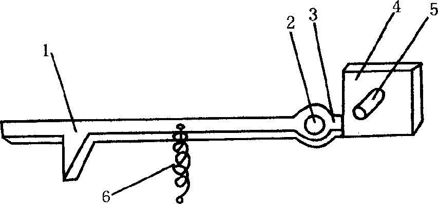
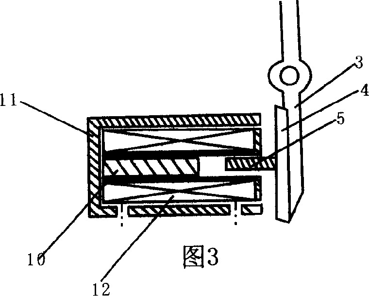
[0030] See attached figure 1 , 3, 4, 6, 12.

[0031] The electromagnet is divided into two parts, fixed and movable. Among them, 2 / 3 of the inner magnet armature column 10 is fixed on the vertical surface of the outer yoke steel plate 11, and 1 / 3 of the inner magnet armature column 5 is connected with the outer magnet steel plate on the other vertical surface. 4 links to each other, and this steel plate is movable, is connected with the outer end of electromagnetic lever movable short arm 3. See Figure 12. Each device of the newly added electronic combination lock is installed on the former lock body of the rolling shutter door after being installed on an iron plate 37. A small cylinder 35 has been added on the telescopic rod of the original rolling shutter door lock, as the control point of this electromechanical combination lock. The control part of the electromechanical combination lock is figure 1Middle electromagnetic lever card 1, electromagnet assembly 2, receive de...

Embodiment 2

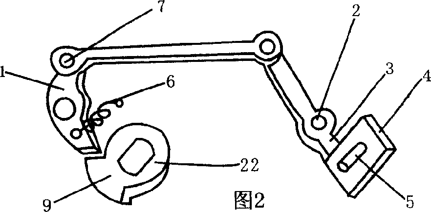
[0033] See accompanying drawing 2,3,4,6,7,8,9,10,11,13,14,15.

[0034] The electronic password alarm control part of the low power consumption electromechanical password anti-theft alarm lock is installed in the lock head. Control the electromagnetic lever card work with the electromechanical password key, do not control the lock core rotating shaft card rotating disk 9 in the locking position, and then do not control the rotation of the lock core rotating shaft 22, and drive the actuator 26 of the lock head to perform the opening and closing action. The lock cylinder shaft has played a very important role. The information input device is installed on the top of the lock cylinder rotating shaft 22, and is integrated with the rotating shaft and the matching mechanical pin area 23. The contacts of information input and channel are all embedded in the middle of the insulating material, and lead wires are connected outside, and are connected to the lock control interface socket N...

Embodiment 3

[0038] see Figure 5 , 6 , 7, 8, 9, 10, 11, 13, 14, 15.

[0039] In this example, an electromechanical password key with remote alarm function is adopted, and a secondary encryption anti-theft alarm control device is installed outside the lock head control interface socket N. The positive power supply is input to the positive working power supply of the electronic combination lock by the 5th head on the N to the positive contact 17. The negative power supply ground wire is introduced into the negative power supply ground wire contact 20 from the fourth head on N. After the key is inserted into the lock, the copper ring 13 on the key not only connects the positive power of the coding transmitter chip on the key, but also provides the positive power of the receiving chip and the control circuit in the lock, so that the electronic combination lock is in working order. The coded pulse output 14 on the key is sent to the receiving decoding control module M after being received b...


PUM


Abstract

Electronic cipher controller is added to available various kinds of mechanical ball lock. In the key and the lock, matched codec chip and information I / One unit are mounted separately, the electronic cipher controls the electromagnet and electromagnetic lever assembly, and the lever assembly performs prior control on the executing mechanism of the lock, so that only when the electronic cipher unit is in unlocking state, can the mechanical lock execute the unlocking program. During locking, the electronic cipher unit is powered off and this results in lowered power consumption and raised safety. The mechanical ball and the electronic cipher may be used simultaneously or alone, and one remote controller may be connected for secondary enciphering. The present invention may be used in where high safety is needed.

Description

Technical field [0001] The invention relates to a password lock, in particular to a low power consumption electromechanical password anti-theft alarm lock. Background technique [0002] Although the existing mechanical pin locks are simple in structure and wide in use, their anti-theft effect is poor. Generally, the anti-theft effect of electronic locks is better, but the power consumption is large when unlocking, and an external AC power supply or high-energy battery is required, which limits the application of electronic locks and has no anti-theft alarm function. Chinese patent CN1059775A "Electronic Lock Micro-power Consumption Control Mechanism" discloses a micro-power consumption control mechanism for electronic locks in the form of electromagnet components. The power consumption drops to the milliampere level. This device must be installed on the newly processed lock, and the shockproof and shockproof effects are relatively poor, and the scope of use is limited. C...

Claims


Application Information

Patent Timeline
Patent Type & Authority Applications(China)
IPC IPC(8): E05B49/02E05B63/14
Inventor 夏爵裕
Owner 夏爵裕
Why Eureka
Try Eureka