Drive unit for hand tool machine

A hand-held machine tool and turbine technology, which is applied in the direction of manufacturing tools, metal processing machinery parts, portable mobile devices, etc., can solve the problems of low efficiency and insufficient vacuum cleaner suction power to meet the requirements, and achieve high power and high grinding The effect of quantity and good overall coordination

Inactive Publication Date: 2005-10-05
ROBERT BOSCH GMBH
View PDF1 Cites 3 Cited by
  • Summary
  • Abstract
  • Description
  • Claims
  • Application Information

AI Technical Summary

Problems solved by technology

[0003] The efficiency of existing hand-held power tools is relatively low, and the suction power that can be provided by the vacuum cleaner is not enough to meet the requirements
Therefore, the high demands on the operating power and the simultaneous dedusting of the workpiece - if this function is designed - are not available for such hand-held power tools

Method used


Image

  • Drive unit for hand tool machine
  • Drive unit for hand tool machine
  • Drive unit for hand tool machine

Examples


Embodiment Construction

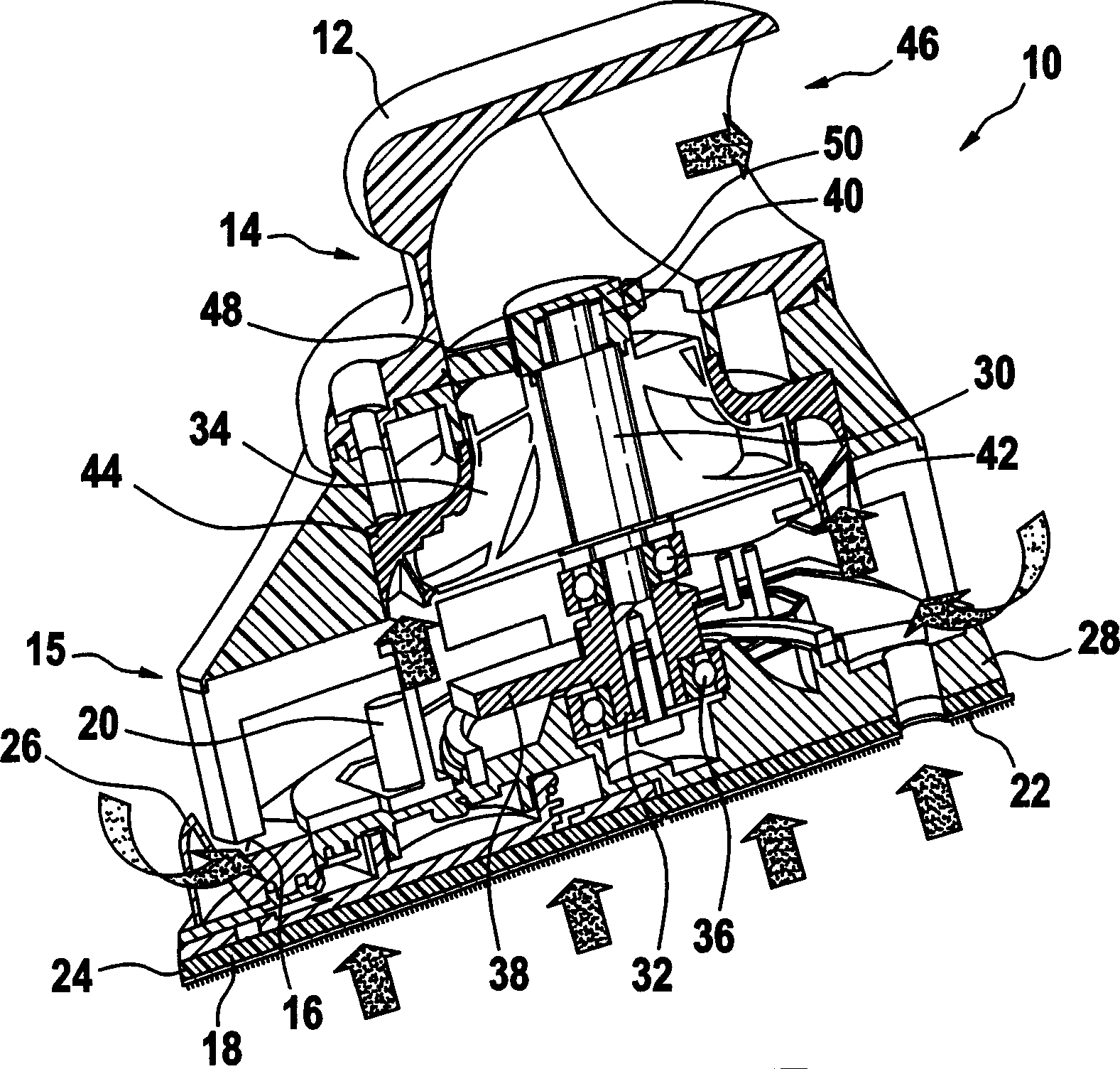
[0040] figure 1 A hand-held power tool 10 is shown, which is designed as a superfinishing machine. It comprises a housing 12 , configured in its upper region as a handle, which continues downwards into a waist-like constriction 14 which is easy to grip and then widens into a bell-shaped region 15 .

[0041] The housing 12 ends at the bottom with a rectilinear lower edge 16 which, in its downward vertical projection, is triangular with outwardly curved sides. Arranged parallel to the lower edge 16 is a grinding disk 18 which is elastically connected to the housing 12 via an elastic vibration element 20 . The grinding disk 18 protrudes with its iron-shaped base in the radial direction out of the vertically downward triangular projection of the lower edge 16 and has clamping means for receiving the sanding disc 22 on its base.

[0042] The grinding disk 18 carries a button 26 on the front central tip 24 , after actuating it, the grinding disk 18 can be removed from the housing ...


PUM


Abstract

A hand tool machine comprises a housing 12 and device (18,22) connected above the housing and reelingly and / or vibratory drivingly installed. The hand tool machine is driven according to rule, in virtue of a sucking airflow, especially a suction cleaner, because a turbine wheel (34) is used as driving device and has special proper inlet, outlet guide grille (44,48), so as to obtain especially fine efficacy.

Description

technical field [0001] The invention relates to a hand-held power tool with a housing carrying a drive unit drivable by means of a pressure medium, in particular by suction air, the latter having a turbine equipped with air blades. Background technique [0002] In patent specification US Pat. No. 6,347,985 B1, a hand-held power tool is known, which is driven only by the suction flow of a common commercial vacuum cleaner. A known Pelton-type turbine is used as the drive for the known hand-held power tool, which turbine uses the suction air flow of the vacuum cleaner to drive the driven spindle or the tool in rotation. [0003] The efficiency of existing hand-held power tools is relatively low, and the suction power that can be provided by vacuum cleaners is not sufficient for the requirements. Therefore, the high demands on the operating power and the simultaneous dedusting of the workpiece—if this function is provided—are not available for such hand-held power tools. Cont...

Claims


Application Information

Patent Timeline
Patent Type & Authority Applications(China)
IPC IPC(8): B23Q5/06B24B23/03B24B47/14B25F5/00
CPCB24B23/03B24B47/14
Inventor 弗兰克·富克斯
Owner ROBERT BOSCH GMBH
Why Eureka
Try Eureka