Power high efficiency grinding head

A high-efficiency, grinding-head technology, used in grinding machines, grinding/polishing equipment, machine tools designed for grinding workpiece rotating surfaces, etc., can solve the problem of weakened spindle rigidity, poor macro quality of the grinding surface, and easy drift of the spindle axis. question

Inactive Publication Date: 2009-09-16
险峰机床厂
View PDF0 Cites 6 Cited by
  • Summary
  • Abstract
  • Description
  • Claims
  • Application Information

AI Technical Summary

Problems solved by technology

The smaller the cutting force is, the lower the rigidity of the spindle will be. Because the axis o

Method used


Image

  • Power high efficiency grinding head
  • Power high efficiency grinding head

Examples


Embodiment Construction

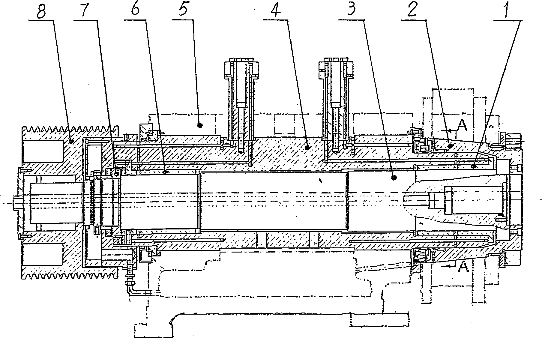
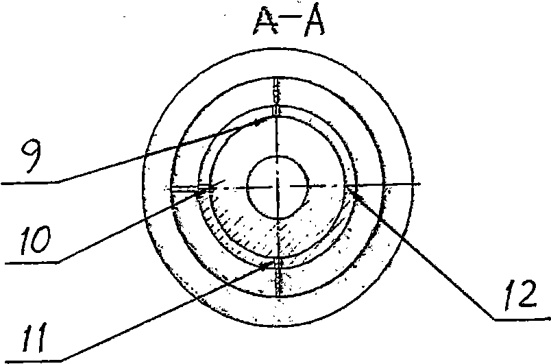
[0016] Such as figure 1 , figure 2 As shown, the main shaft 3 is installed in the eccentric sleeve 4, the dynamic and static pressure front bearing 1 is installed at the front end between the eccentric sleeve and the main shaft, the dynamic and static pressure rear bearing 6 and the rolling thrust bearing 7 are installed at the rear end, and then put into the mill frame shell together 5. Install the tapered sleeve 2 on the front end of the eccentric sleeve 4, and install the pulley 8 on the rear end of the main shaft 3. The structure of the oil chamber of the dynamic and static pressure bearing is 9 static pressures in the upper chamber, 11 static pressures in the lower chamber, 10 static pressures in the front chamber and 10 static pressures in the rear chamber. Chamber 12 dynamic pressure.


PUM


Abstract

A power high efficiency grinding head belongs to an excircle grinding head. A main shaft (3) is mounted in an eccentric sleeve (4); a dynamic and static pressure front bearing (1) is mounted at the front end between the eccentric sleeve and the main shaft; the rear end is equipped with a dynamic and static pressure rear bearing (6) and a roll push bearing (7). All the components are mounted in a grinding rack housing (5). The front end of the eccentric sleeve (4) is equipped with a taper sleeve. The rear end of the main shaft (3) is equipped with a belt wheel (8). The structure format of the dynamic and static pressure beating oil chamber is that an upper chamber (9) is the static pressure, a lower chamber (11) is the static pressure, a front chamber (10) is the static pressure and a rear chamber (12) is the dynamic pressure. This invention improving the own rigid and the interference rejection of the grinding head is suitable for the power grinding so as to improve the grinding efficiency of the roller and the surface macroscopic quality of the roller, and to realize the grinding effect of machining-less of the middle and high rollers with the surface roughness concentration of Ra 0.03, and it is suitable for the excircle surface of the grinding roller.

Description

Technical field: [0001] The invention relates to a cylindrical grinding head, in particular to a powerful and efficient grinding head. Background technique: [0002] In the prior art, the structure of the oil chamber of the main shaft bearing of the static pressure eccentric sleeve is three chambers of static pressure and one chamber of dynamic pressure, and the generation of the dynamic pressure effect is mainly realized by the eccentricity of the main shaft. Due to the relatively small parameters such as the size and pressure of the relevant shafting system, its anti-interference performance is poor. Under a certain spindle bearing clearance, the greater the cutting force, the better the rigidity of the spindle bearing. The smaller the cutting force is, the lower the rigidity of the spindle will be. Because the axis of the spindle is easy to drift, the macroscopic quality of the grinding surface is relatively poor. In addition, factors such as spindle bearing clearance, b...

Claims


Application Information

Patent Timeline
IPC IPC(8): B24B5/37
Inventor 杨昌祥周安刚付恒勋章群渝周钢武龙有生雷起相
Owner 险峰机床厂
Why Eureka
Try Eureka