Method of seaming a knitted fabric piece

A technology of piece head and knitted fabric, which is applied in the field of trimming of knitted piece head

Active Publication Date: 2005-10-05
KARL MAYER STOLL R&D GMBH
View PDF0 Cites 4 Cited by
  • Summary
  • Abstract
  • Description
  • Claims
  • Application Information

AI Technical Summary

Problems solved by technology

However, especially for cylindrical-circular-finished knitted fabrics, these requirements cannot be fully met according to the prior art sleeve method (Kettelverfahren).

Method used


Image

  • Method of seaming a knitted fabric piece
  • Method of seaming a knitted fabric piece
  • Method of seaming a knitted fabric piece

Examples


Embodiment Construction

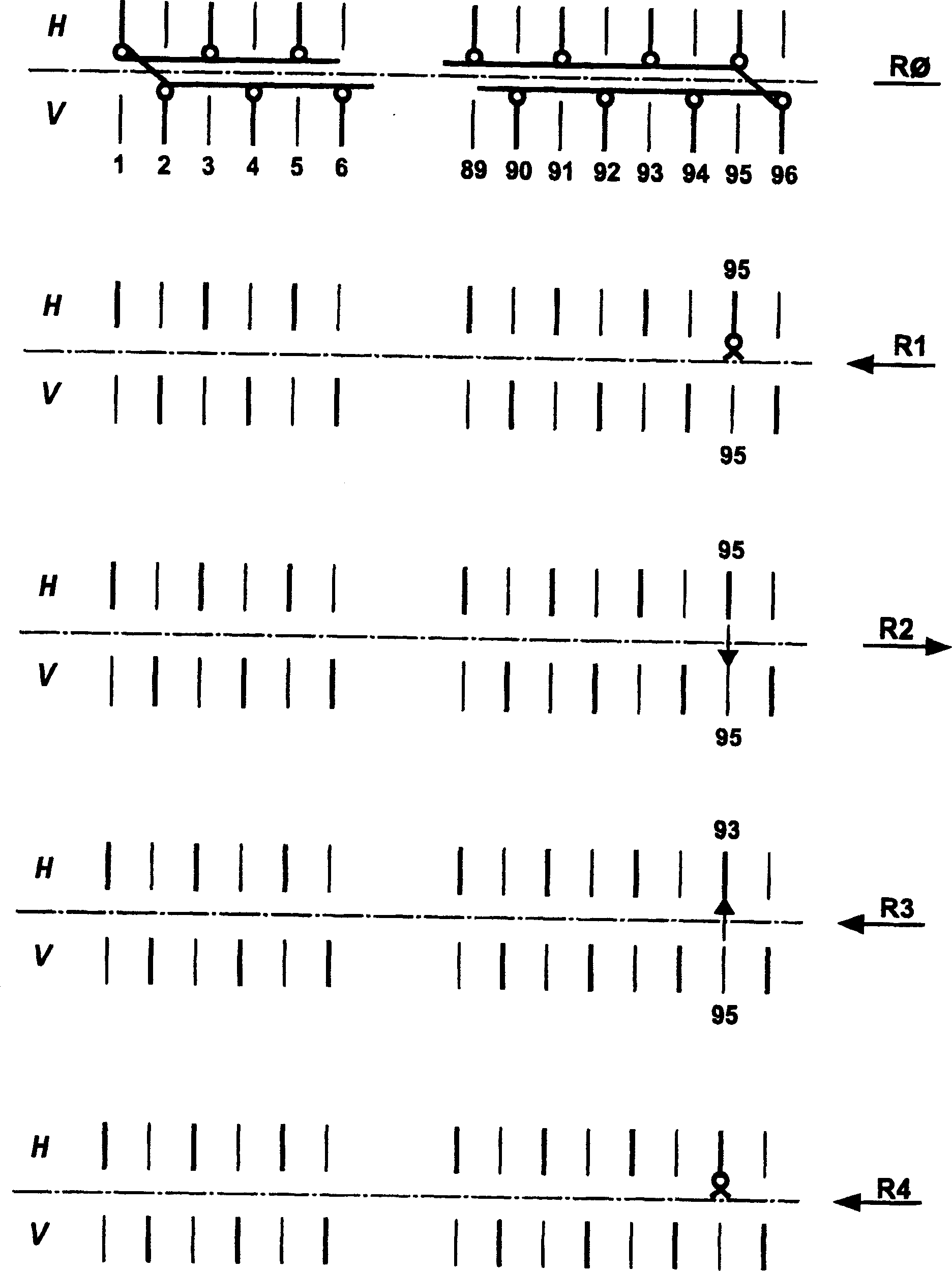
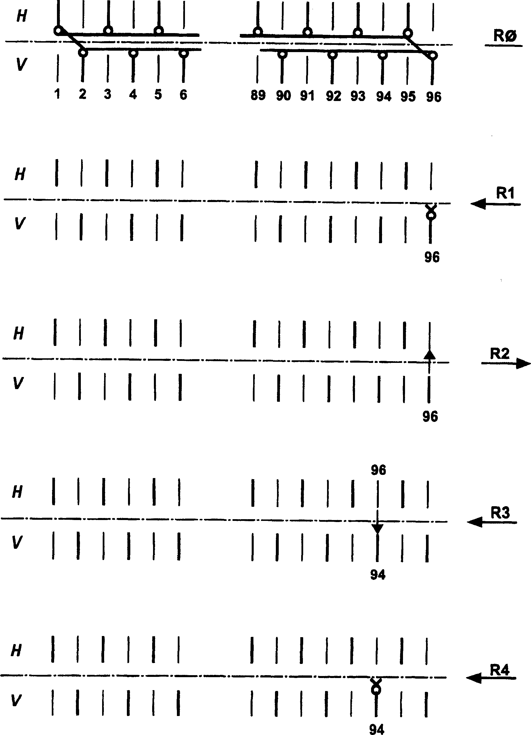
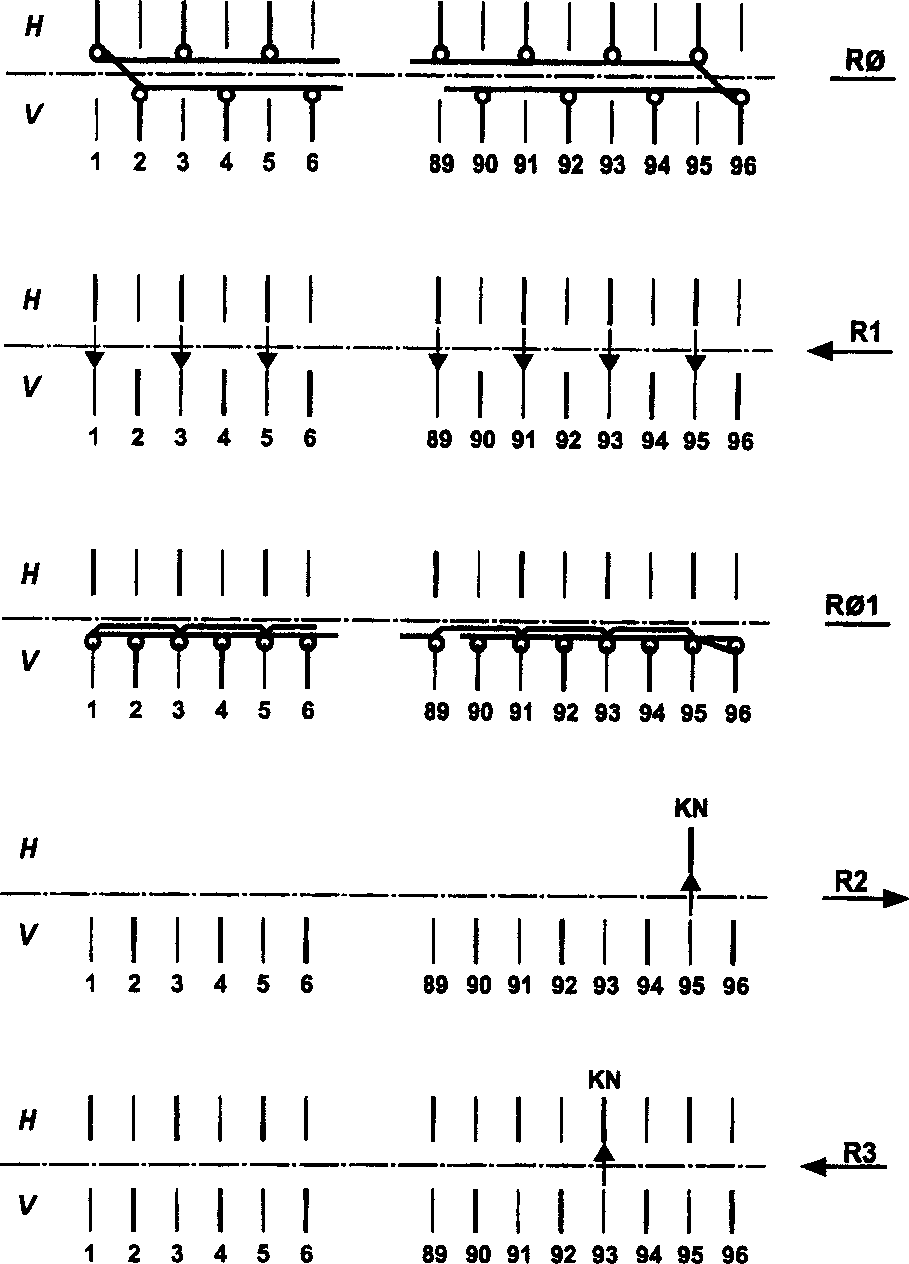
[0018] Figure 1.1 with Figure 1.2 Using the example of a tubular knitted fabric, the edge technology according to the prior art for forming a firm knit finish, which is required, for example, at a neckline or cuff, is illustrated. This second needle bed, here the rear needle bed H, can perform a traversing movement. The front needle bed V is then non-traversable in the example described. Of course, the roles of needle bed V and H can also be exchanged. Furthermore, it is also possible in principle to arrange the two needle beds so that they can be offset.

[0019] exist Figure 1.1 In the R0 course of , the last knitting course of the tubular-circular-finished knitted fabric is indicated. The fabric is constructed on the front and rear needle beds V, H. Each of the needles with a loop is aligned with an empty needle of the other needle bed. In the course R1, the back side of the knitted fabric on the rear needle bed H is trimmed. For this purpose, the outermost needles...


PUM


Abstract

In a knitting process a knitted flat panel is produced on a needle bed from which it is finally cast off by looping a starting warp stitch on a second needle bed (H, V) not bearing thread. The second needle bed is then shifted towards the next line to be cast off on the first needle bed. The next line to be cast off is then dropped to the line of needles. The two joined lines are then cast off, forming a new common seam.

Description

technical field [0001] The invention relates to a method for trimming a piece of knitted goods on a flat knitting machine having at least two opposing needle beds. Background technique [0002] Different trimming methods are already known which require two stitch transfer processes for trimming a loop. They are thus relatively time-intensive. These time-intensive methods are undesirable especially when producing cylindrical-circular finished knitted goods. These knitwear are entirely constructed on flat knitting machines. The total machine operating time required for its production then consists of the combination of the time for the movement of the slide bar forming the knitting course and the time for the movement of the slide bar in which only the stitches are transferred. In order to be able to produce the entire piece of knitted goods economically, the time for the movement of the slider without loop formation must be minimized as much as possible. [0003] At the s...

Claims


Application Information

Patent Timeline
IPC IPC(8): D04B1/00D04B1/22D05B7/00
CPCD04B1/22
Inventor H·施密德特T·诺嫩马赫尔F·科卢拉
Owner KARL MAYER STOLL R&D GMBH
Why Eureka
Try Eureka