Device and method for removing dust for mining train loading station

A technology of dust removal device and loading station, which is applied in separation methods, chemical instruments and methods, and the use of liquid separation agents, etc. It can solve the problems of occupying a large working space, unsatisfactory dust removal effect, and harsh use conditions, and achieves simple installation, Dust removal implementation time is short and the effect of high reliability

Active Publication Date: 2017-02-22
山西中永通机电设备制造有限公司
View PDF17 Cites 1 Cited by
  • Summary
  • Abstract
  • Description
  • Claims
  • Application Information

AI Technical Summary

Problems solved by technology

[0006] However, further research shows that the above-mentioned prior art still has the following defects or deficiencies: the above-mentioned existing dust removal device needs to occupy a large working space, the original system needs to be refitted, the operability is poor, and the service conditions are harsh, which is easy to cause secondary damage. secondary pollution, and the dust removal effect is not ideal, which cannot satisfy the objective process of continuous dust generation in the continuous production process

Method used


Image

  • Device and method for removing dust for mining train loading station

Examples


Embodiment approach 1

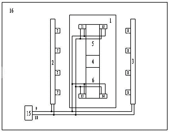
[0032] The device consists of an open train compartment 1, a spray dust removal device and an air-water distribution device on the left side 2, a spray dust removal device and an air-water distribution device 3 on the right side, a chute for materials to be loaded 4, a swingable feeding device 5 before the materials, and a Rear swingable feeding device 6, left water vapor atomization nozzle group 7, right water vapor atomization nozzle group 8, pressure water main pipe 9, pressure gas main pipe 10, material front swingable feeding device left water vapor atomization nozzle 11. Water vapor atomization nozzle on the right side of the swingable feeding device before the material 12. Water vapor atomization nozzle on the left side of the swingable feeding device after the material 13. Water vapor atomization nozzle on the right side of the swingable feeding device after the material 14. Intelligent spray control The device 15 is composed of a loading structure 16. The open-ended tr...

Embodiment approach 2

[0037] The left water vapor atomization nozzle group 7 constitutes 5 nozzles, the right water vapor atomization nozzle group 8 constitutes 5 nozzles, and the pressure water is 3.5kgf / cm 2 , the working pressure range of compressed air is 4kgf / cm 2 , the water-gas volume ratio is 100:2, and the water-gas atomizing nozzle group 8 on the right side acts together on the upper part of the train open compartment 1 to form a 200 mm higher than the open compartment, and the others are the same as in Embodiment 1.

Embodiment approach 3

[0039] The left water vapor atomization nozzle group 7 consists of 6 nozzles, the right water vapor atomization nozzle group 8 consists of 6 nozzles, and the pressure water is 2.5kgf / cm 2 , the working pressure range of compressed air is 3.5kgf / cm 2 , the water-gas volume ratio is 100:3, and the water-gas atomizing nozzle group 8 on the right side acts together on the upper part of the train open compartment 1 to form a 10 mm higher than the open compartment, and the others are the same as in Embodiment 1.


PUM


Abstract

The invention provides a device and method for removing dust for a mining train loading station, and belongs to the field of dust removing devices and methods. The device is characterized in that dust in a restricted space is removed by using vapor atomized fluid as dust-removing energy and compressed air as a main energy source, the moisture content in the device has little influence on loaded materials, and the formed air-water atomized density wave can be used for closing the path of coal dust which is diffused and migrated from the opening at the upper part of a train in the coal loading process and gathering new dust-removing energy to constantly and repeatedly remove dust along the main direction of density wave diffusion. The device for removing dust for the mining train loading station is simple to assemble and convenient to maintain, can be used for solving the problem which is urgent to be solved in the prior art, and can be used for removing dust in the restricted space with high reliability, no secondary pollution and strong implementation. The device and method can realize all-weather maintenance-free long-term and stable work, and are widely applicable to systems and industries of mines, agriculture, petrochemical engineering, metallurgy, electricity, pharmacy, environmental protection and the like.

Description

technical field [0001] The invention relates to a dedusting device and a dedusting method at a mining train loading station, which belong to the field of dedusting devices and methods, and more specifically, relate to a dedusting device and a dedusting method at a mining train loading station. Background technique [0002] In the process of taking out the materials from the finished product warehouse and loading them into the train, the transportation process of the materials is continuous. In order to load the materials into the open compartment smoothly, the materials need to be pre-loaded into a silo that is higher than the train compartment and equipped with a chute device at the bottom. The nature of the loading device, in order to adapt to the material loading, a swingable feeding device is usually installed along the direction of the train at the lower part of the chute to ensure better material loading. The source of dust kinetic energy is mainly potential energy and ...

Claims


Application Information

Patent Timeline
IPC IPC(8): B01D47/06
CPCB01D47/06
Inventor 郭建珠樊智慧高云峰田国政赵晓兵
Owner 山西中永通机电设备制造有限公司
Why Eureka
Try Eureka