

Ventilation system
A technology of ventilation system and air supply port, which is applied in the direction of ventilation system, space heating and ventilation, space heating and ventilation details, etc. It can solve the problems of existing occupants and difficulty in ensuring the location of the air supply unit, and achieves the reduction of up and down The effect of temperature difference
- Summary
- Abstract
- Description
- Claims
- Application Information
AI Technical Summary
Problems solved by technology
Method used
Image

Examples
Embodiment
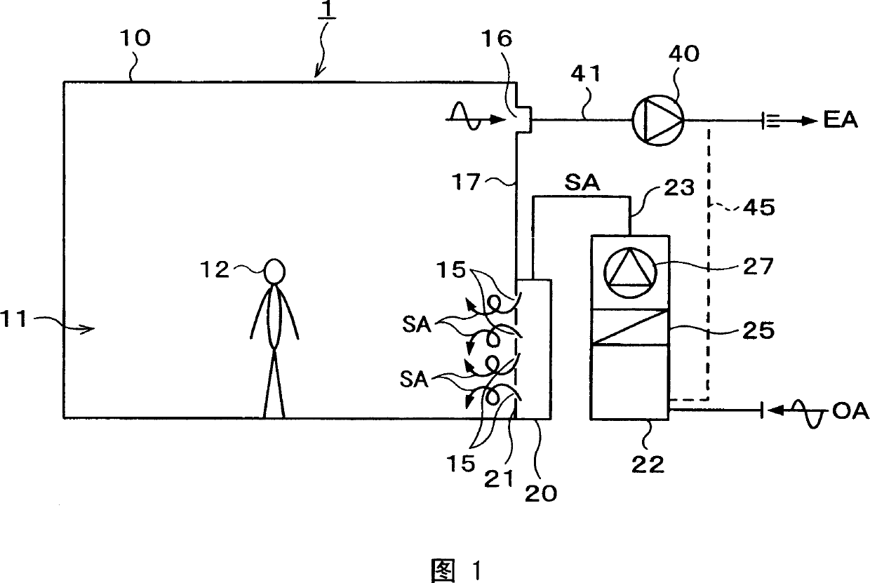
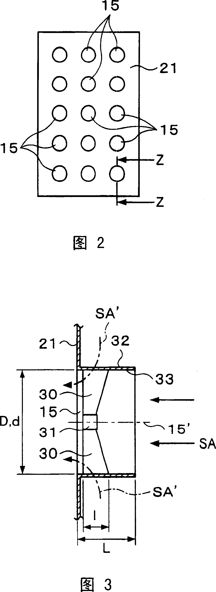
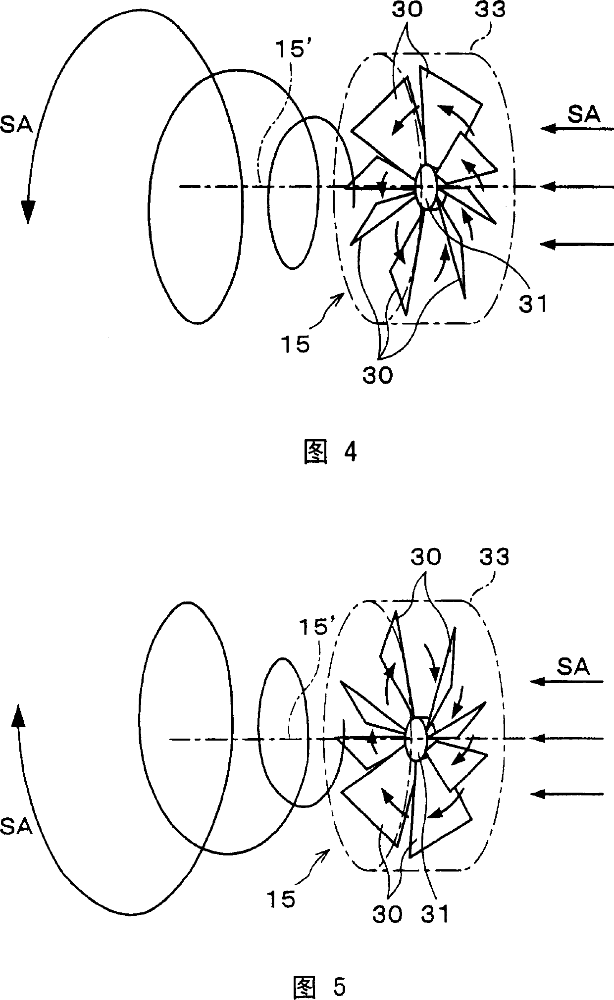
[0086] As shown in Figure 19, the air supply unit is arranged on a floor with a plan view of 15m x 16m, and a partition (non-air-conditioned space) of 7.1m x 7.2m is formed on a part of the interior. The floor area is 190m 2 , In the air-conditioned space (machine studio) 10 with a ceiling height of 10 m, nozzles with a diameter of 500 mm that blow out air supply horizontally were installed at a position with a height of 4 m, and air conditioning by these air supply units and nozzles was performed. The air supply unit of the embodiment of the present invention was compared with the air supply unit of the conventional comparative example 1. The air supply unit of the present invention has an air supply port formed on the front of the width of 0.6m and a height of 2.1m, and is installed on each air supply port. In the air supply unit with a plurality of guide vanes that impart a rotational component to the low-temperature air SA, the circumference of the guide vanes is surrounded...
PUM
 Abstract
Description
Claims
Application Information