Phase-locking loop with frequency-control sensitivity compensation ability

A phase-locked loop and loop technology, applied in the automatic control of power, electrical components, etc., can solve problems such as the decrease of the stability of the loop bandwidth value W and the excessive fluctuation range of the loop bandwidth W value

Active Publication Date: 2005-10-05
MEDIATEK INC
View PDF1 Cites 0 Cited by
  • Summary
  • Abstract
  • Description
  • Claims
  • Application Information

AI Technical Summary

Problems solved by technology

However, when the PLL system is integrated into an integrated circuit (Integrated Circuit, IC), it is found that the VCO gain value K VCO The linearity is severely affected, causing the control signal V at the frequency of interest t range, the VCO gain value K VCO (like figure 2 shown) cannot be approximated to a certain value, at this time, even if the phase detector ...

Method used


Image

  • Phase-locking loop with frequency-control sensitivity compensation ability
  • Phase-locking loop with frequency-control sensitivity compensation ability
  • Phase-locking loop with frequency-control sensitivity compensation ability

Examples


Embodiment Construction

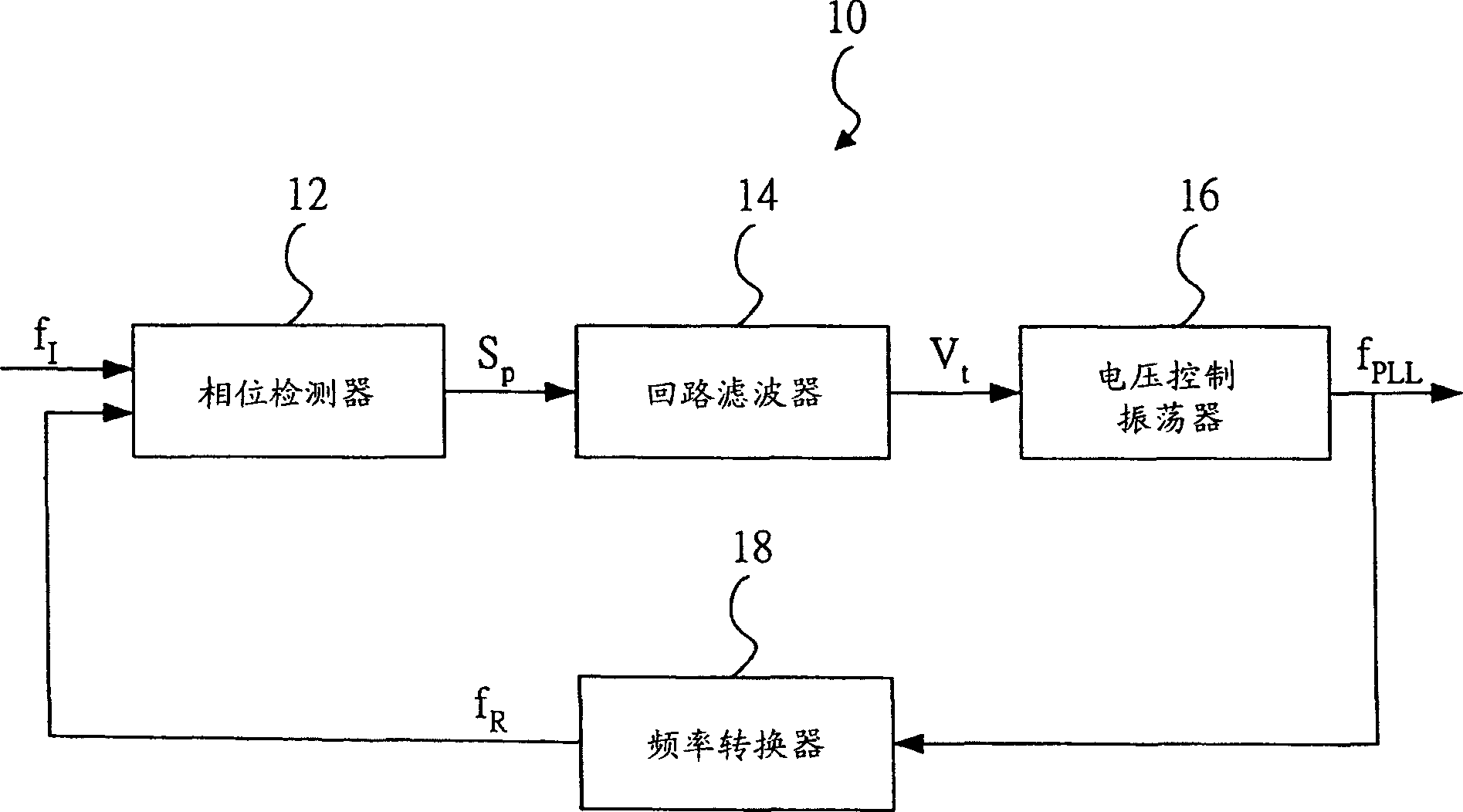
[0067] see Figure 6 , Figure 6 is a system block diagram of the PLL 30 of the first embodiment of the present invention. The present invention provides a PLL 30 including a phase detector 32 , a loop filter 34 , a gain controller 36 , a VCO 38 and a frequency converter 40 .

[0068] The phase detector 32 is an analog phase detector for receiving a first feedback signal F fb , a reference signal F ref and a gain control signal S gc , output a phase difference signal S p , phase difference signal S p Response to the first feedback signal F fb with reference signal F ref The phase difference between two signals. A phase detector gain value K of the phase detector 32 PD Defined as the phase difference signal S p Ratio to phase difference. Phase detector gain value K PD can be controlled by the gain signal S gc adjusted.

[0069] The implementation of the phase detector 32 is not the focus of the present invention, and will not be discussed in detail here because it...


PUM


Abstract

Based on functional relation of a loop bandwidth value of phase lock loop with gain value of phase detector and gain value of voltage controlled oscillator (or sensitivity of controlling frequency), adjusting gain value of phase detector to compensate fluctuation of gain value of voltage controlled oscillator so as to make loop bandwidth value more stable.

Description

technical field [0001] The present invention relates to a phase-locked loop (Phase-Locked Loop, PLL), in particular to a PLL capable of compensating frequency control sensitivity (Tuning Sensitivity), so as to obtain a more stable loop bandwidth (Loop Bandwidth). Background technique [0002] In a communication system, a PLL is a device used to generate an output signal with a specific phase and a specific frequency, and for this purpose, the loop bandwidth W of the PLL should be maintained as much as possible within the frequency range of the PLL input signal of interest smooth. [0003] Please refer to figure 1 , which shows a system block diagram of a conventional PLL 10 . The conventional PLL 10 includes a phase detector (Phase Detector) 12 , a loop filter (Loop Filter) 14 , a voltage controlled oscillator (Voltage Controlled Oscillator, VCO) 16 , and a frequency converter (Frequency Converter) 18 . The phase detector 12 simultaneously receives an input frequency f I...

Claims


Application Information

Patent Timeline
IPC IPC(8): H03L7/08H03L7/099
Inventor 郭仓甫曾柏森王守琮柯凌维
Owner MEDIATEK INC
Why Eureka
Try Eureka