Light guide plate and backlight device

A technology of backlight device and light guide plate, applied in the field of light guide plate, which can solve the problem of small light ratio

Inactive Publication Date: 2005-10-05
HITACHI CHEM CO LTD
View PDF2 Cites 20 Cited by
  • Summary
  • Abstract
  • Description
  • Claims
  • Application Information

AI Technical Summary

Problems solved by technology

[0012] In the conventional light guide plate, the ratio of the light emitted from the exit surface to the light incident from the incident surface is very small, and there is a problem in the utilization efficiency of the light emitted from the light source.

Method used


Image

  • Light guide plate and backlight device
  • Light guide plate and backlight device
  • Light guide plate and backlight device

Examples


no. 1 example

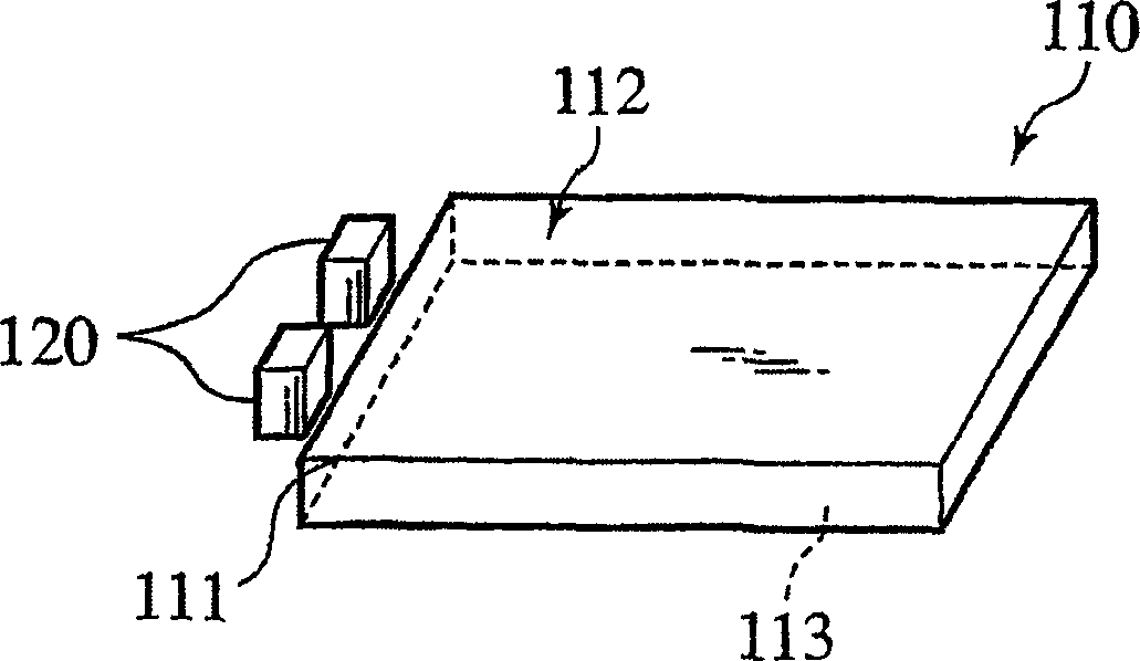
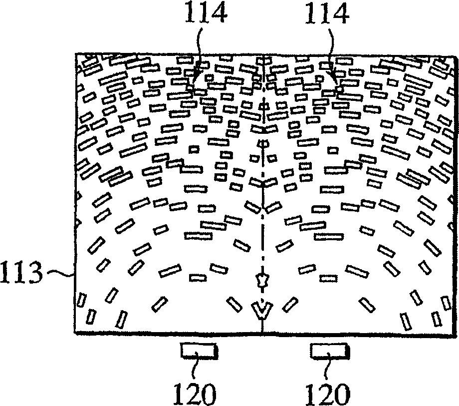
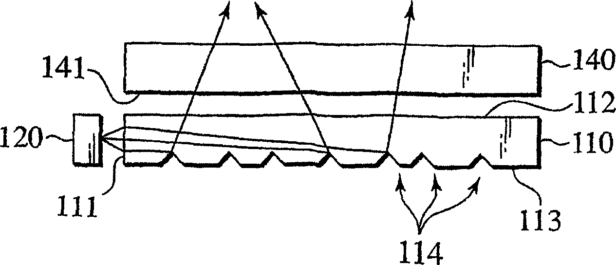
[0120] First, a first embodiment of the present invention will be described. In the first embodiment, the notch surface (round shape) formed on one side surface of the apex of the substantially rectangular light guide plate is used as the incident surface, and the light incident on the light guide plate from one light source repeats total reflection while repeating total reflection. Entering the light guide plate, every time it is reflected by the reflection groove, the angle will gradually rise, so that the angle relative to the exit surface will gradually become smaller, and it will exit from the exit surface as soon as the critical angle is reached.

[0121] Figure 3A , Figure 3B And FIG. 3C is a diagram showing the outline of the light guide plate of the first embodiment. A light emitting diode (LED) 20 of the light source is also shown in the figure at the same time.

[0122] Figure 3A is a top view of the light guide plate 10, Figure 3B 3C is a front view of the...

no. 2 example

[0182] Next, a second embodiment of the present invention will be described. In the second embodiment, the notch surface formed on one side surface of the vertex of the substantially rectangular light guide plate is used as the incident surface, and the light incident on the light guide plate from one light source enters the light guide plate while repeating total reflection, If it is reflected by the reflection groove, it will emerge from the exit surface at a small exit angle.

[0183] In addition, since this embodiment has the same structure as the above-mentioned first embodiment except for the reflective groove, the same symbols are attached to the common parts and their descriptions are omitted.

[0184] Figure 15A, Figure 15B And FIG. 15C is a schematic view showing the light guide plate of the second embodiment. A light emitting diode (LED) 20 of the light source is also shown in the figure.

[0185] 15A is a top view of the light guide plate 10, Figure 15B is a ...

no. 3 example

[0200] Next, a third embodiment of the present invention will be described. In the third embodiment, one side surface of the substantially rectangular light guide plate 10 is used as the incident surface, and light incident on the light guide plate from a plurality of light sources enters the light guide plate while repeating total reflection, and is reflected by the reflection groove. When , the angle will be gradually erected, so that the angle relative to the exit surface will gradually become smaller, and when the critical angle is reached, it will exit from the exit surface.

[0201] In addition, since the present embodiment has the same structure as that of the above-mentioned first embodiment except for the arrangement of the light source and reflection grooves, etc., the common parts are given the same reference numerals and their descriptions are omitted.

[0202] Figure 18A , Figure 18B And FIG. 18C is a schematic view showing the light guide plate of the third e...


PUM


Abstract

A light guide plate 10 comprising an entry surface 11 on at least one side surface, a rectangular exit surface 12 orthogonal to the entry surface 11 and a reflecting surface 13, wherein the reflecting surface 13 has a deflection pattern that receives a ray of light incoming from the entry surface 11 or the exit surface 12 at a certain angle to the normal to the exit surface 12 and outputs the ray of light at a reduced angle to the normal, the deflection pattern has a plurality of arcuate deflection pattern elements formed on a plurality of concentric circles, the exit surface 12 has an anisotropic diffusion pattern that transmits so as to spread, a ray of light incoming from the deflection pattern at an angle up to a specified angle with respect to the normal the exit surface 12, the anisotropic diffusion pattern spreads the ray of light incoming from the deflection pattern so that the width of diffusion in a direction orthogonal to the radial direction of arcs of the concentric circles is larger than that in the radial direction, and the center of the concentric circles is positioned on any one of the side surfaces of the light guide plate 10 or in the vicinity thereof.

Description

technical field [0001] The present invention relates to a light guide plate for introducing light emitted from a light source, and a backlight device provided with the light guide plate for illuminating liquid crystal display elements and the like from the back. Background technique [0002] Conventionally, in order to illuminate liquid crystal display devices such as mobile phones, a light guide plate for guiding light emitted from a light source to the liquid crystal display device and a backlight device for illuminating the liquid crystal display device including the light guide plate from the back are provided. [0003] Figure 1A , Figure 1B And FIG. 1C is an external view showing a conventional light guide plate (for example, refer to Japanese Patent No. 3151830.). Figure 1A represents a stereogram, Figure 1B Indicates a top view. Figure 1A The light emitting diode 120 of the light source is also represented in the same time. [0004] The light guide plate 110 is...

Claims


Application Information

Patent Timeline
Patent Type & Authority Applications(China)
IPC IPC(8): F21V8/00G02B6/00G02F1/13357
CPCG02F1/133615G02B6/0036G02B6/0038G02F1/1335
Inventor 杉本靖手岛照雄土桥友牧岛和宏小松德太郎远藤俊博
Owner HITACHI CHEM CO LTD
Why Eureka
Try Eureka