Check patentability & draft patents in minutes with Patsnap Eureka AI!

Pixel structure in an electroluminescent display device

An electroluminescent device and luminescent technology, applied in the direction of electroluminescent light source, electric solid device, electric light source, etc., to achieve the effect of prolonging the life of the display and prolonging the life

Inactive Publication Date: 2005-10-12
KONINKLIJKE PHILIPS ELECTRONICS NV
View PDF2 Cites 3 Cited by
  • Summary
  • Abstract
  • Description
  • Claims
  • Application Information

AI Technical Summary

Problems solved by technology

In fact, the sub-pixel comprising the electroluminescent material with the shortest decomposition time scale thus controls the lifetime of the display

Method used


Image

  • Pixel structure in an electroluminescent display device
  • Pixel structure in an electroluminescent display device
  • Pixel structure in an electroluminescent display device

Examples


Embodiment Construction

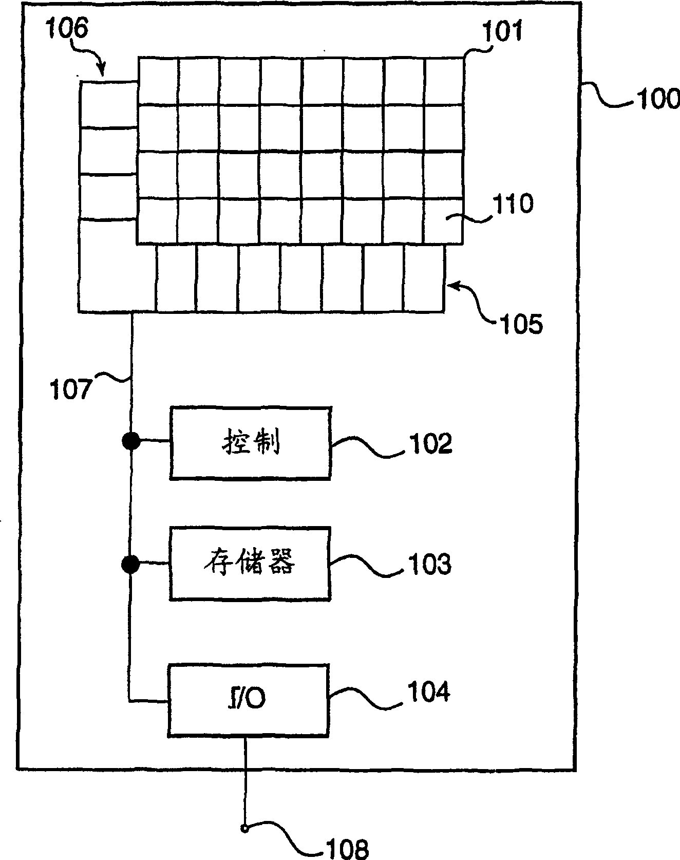
[0026] figure 1 An electronic device 100 including an electroluminescent color display device 101 according to the present invention is shown. The device 100 is intended to be described in a general manner, in order to emphasize the fact that a display unit according to the invention, when implemented by a skilled person, can be applied to any electronic device, such as a computer or a communication terminal.

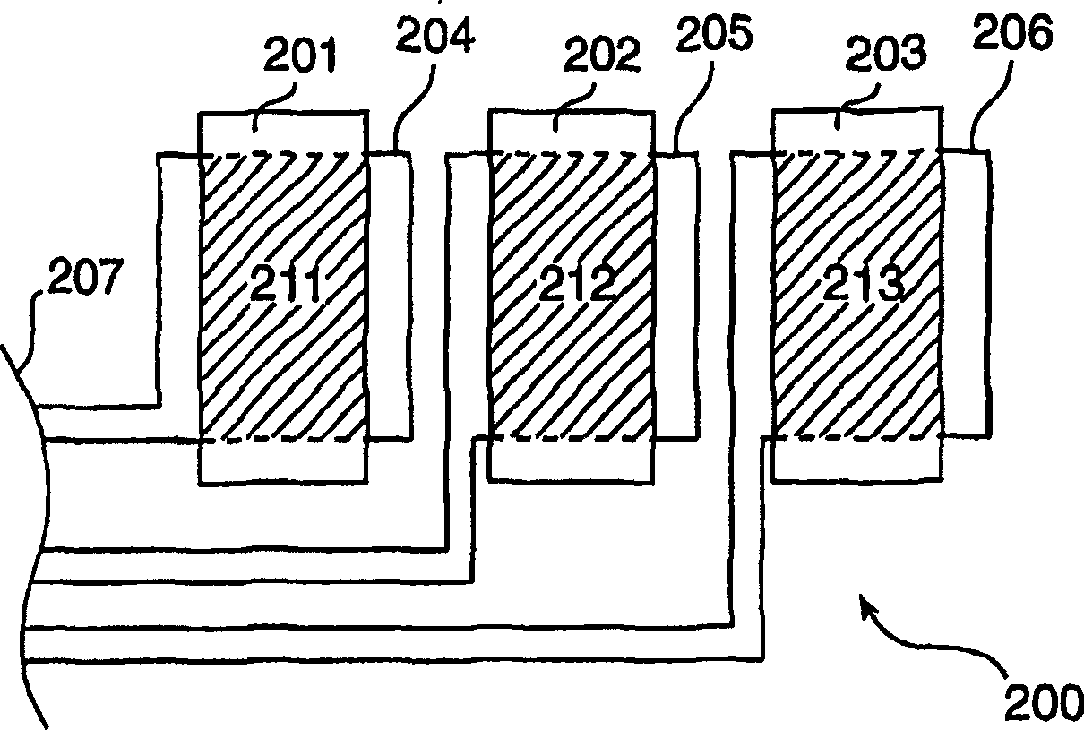
[0027] A control unit 102 utilizes the contents of the storage unit 103 and exchanges information with, for example, an external data source via a connector 108 of the input / output interface unit 104 . Via a data bus 107 , the control unit 102 provides signals to the row and column signal transmission lines 105 , 106 , delivering current to the picture element matrix 110 of the electroluminescent device 101 . Those skilled in the art will appreciate that the image unit 110 includes many separate components, several of which will be combined below figure 2 Discuss fur...


PUM


Abstract

An electroluminescent device (200) for use, e.g., in a colour matrix display unit is presented. Picture elements comprise a plurality of electroluminescent sub-pixels (201,202,203) capable of emitting light when subject to electric current. The sub-pixels each have a degradation lifetime and an emissive area (211,212,213) and, for any pair of first and second sub-pixels in a picture element, the ratio between the first sub-pixel emissive area and the second sub-pixel emissive area is inversely proportional to the ratio between the degradation lifetime of said first sub-pixel and the degradation lifetime of the second sub-pixel.

Description

technical field [0001] The present invention relates to a device comprising at least one picture element comprising a plurality of electroluminescent sub-pixels. Background technique [0002] Since the discovery in the early 1990s, there have been many research and development results in light-emitting devices utilizing electroluminescent materials, organic materials such as polymers, and inorganic materials. Products including such devices are now becoming commonly available. Examples of such products include mobile communication terminals, PDAs, etc., which are equipped with monochrome or color matrix display devices. [0003] The main advances that have been made in the development of electroluminescent devices have been in the area of ​​reduction in driving voltage and increased efficiency of conversion from electrical energy input to light energy emitted from the device. [0004] In a typical color matrix display device with electroluminescent light emitting diodes, e...

Claims


Application Information

Patent Timeline
Patent Type & Authority Applications(China)
IPC IPC(8): H05B33/12G09F9/30G09G3/20G09G3/30G09G3/32G09G5/02H01L27/32H01L51/50H05B33/14
CPCG09G3/3208G09G2300/0443G09G2320/043G09G3/3225G09G3/3216G09G3/30G09G5/02G09G3/2074G09G3/10G09G3/20
Inventor C·T·H·F·里伊登鲍姆
Owner KONINKLIJKE PHILIPS ELECTRONICS NV
Features
  • R&D
  • Intellectual Property
  • Life Sciences
  • Materials
  • Tech Scout
  • Unparalleled Data Quality
  • Higher Quality Content
  • 60% Fewer Hallucinations
Learn More