Check patentability & draft patents in minutes with Patsnap Eureka AI!

Continuous resistance wire probe and making method thereof

A manufacturing method and resistance wire technology, which are applied to devices using electric/magnetic methods, devices that measure the time required to move a certain distance, etc., can solve problems such as short circuits, improve reliability, simplify the test process, and improve the reliability of the test process. volume reduction effect

Active Publication Date: 2015-06-24
DALIAN UNIV OF TECH
View PDF2 Cites 0 Cited by
  • Summary
  • Abstract
  • Description
  • Claims
  • Application Information

AI Technical Summary

Problems solved by technology

[0004] The purpose of the present invention is to provide a continuous resistance wire probe for measuring explosive detonation waves and shock waves, mainly to solve the problem of early short circuit caused by the advance shock wave burning the resistance wire

Method used


Image

  • Continuous resistance wire probe and making method thereof
  • Continuous resistance wire probe and making method thereof
  • Continuous resistance wire probe and making method thereof

Examples


Embodiment 1

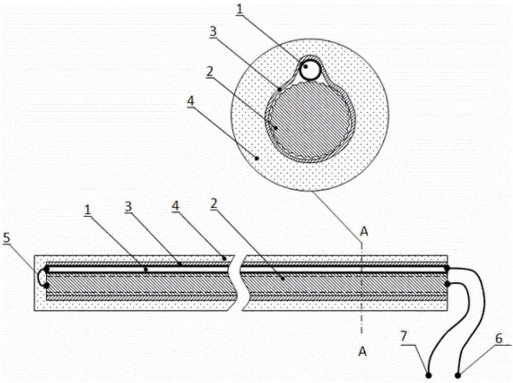
[0030]Take a circular stainless steel wire rope with a diameter of 0.5mm and a length of 0.9m as the twist-shaped metal wire 2; take a constantan polyester enameled wire with a diameter of 0.05mm and a length of 1m as the enamelled resistance wire 1, and measure its resistance value ρ=245.0 Ω / m; Take copper foil with a thickness of 0.015mm as the shielding layer 3, and extrude it into a wire with a diameter of 1.5mm; take a polyvinyl chloride heat shrinkable sleeve with a length of 0.9m as the insulating shell layer 4.

[0031] ①Remove the insulating paint from both ends of the enamelled resistance wire 1 by 10mm, weld the first end to the first end of the twisted metal wire 2 as the conduction terminal 5, the end of the resistance wire as the lead terminal A6, and the end of the twisted metal wire 2 as the lead terminal B7 ;

[0032] ② Wind the enamelled resistance wire 1 and the twist-shaped metal wire 2 together with a winding machine;

[0033] ③ Wrap the shielding layer 3...

Embodiment 2

[0041] Take a stainless steel square steel wire with a side length of 0.3mm and a length of 0.9m as the core wire; take a constantan polyester enameled wire with a diameter of 0.05mm and a length of 1m as the enamelled resistance wire 1, and measure its resistance value ρ=245.0Ω / m; Copper foil with a thickness of 0.015mm is used as the shielding layer 3, and a polyvinyl chloride heat-shrinkable sleeve with a length of 0.9m is used as the insulating shell layer 4.

[0042] ① Vacuum annealing and twisting of stainless steel square steel wire to make twist-shaped metal wire 2 with a pitch of 0.25mm, degreasing and pickling.

[0043] ②Remove 10mm of insulating varnish from both ends of the enamelled resistance wire 1, and weld the first end with the twist-shaped metal wire 2 as the conduction terminal 5, the end of the resistance wire as the lead terminal A6, and the end of the twist-shaped metal wire 2 as the lead terminal B7 ;

[0044] ③ Wrap the twist-shaped metal wire 2 and ...


PUM


Abstract

A continuous resistance wire probe and a making method thereof belong to the technical field of detonation and are characterized in that a fried dough twist-shaped metal wire is used as a core wire, an enameled resistance wire is paved on the core wire, then a conductive film is tightly wound to form a shielding layer, and a flexible insulation layer wraps the shielding layer, so a linear continuous resistance wire probe is made. A screw rod wire, a twisted wire, a fine steel rope, a wrapping wire string or a triangular to hexagonal fried dough twist-shaped metal wire twisted according to a fixed pitch is adopted as the fried dough twist-shaped metal wire; the enameled resistance wire is adopted as the resistance wire; a metal foil or a metal-coated plastic film or conductive rubber is adopted as the shielding layer; commonly used insulation materials such as rubber or plastic are used as the external insulation layer. The resistance wire probe is a universal induction part, can be used for measuring both a detonation wave and measuring a high-pressure impact wave. The continuous resistance wire probe has the beneficial effects that the problem that the resistance wire is burnt to be broken or through in advance is solved, the reliability of measuring data is improved, the length of the probe is not limited and the continuous resistance wire probe is more suitable for the large-scale measuring in an actual detonation field.

Description

technical field [0001] The invention belongs to the technical field of blasting, and relates to a continuous resistance wire probe, in particular to a general resistance wire probe suitable for continuously measuring the detonation wave velocity of explosives and the shock wave velocity of an incoming medium at an actual blasting site. Background technique [0002] The continuous resistance wire measurement method has been widely used in the field of explosion shock. For example, as early as the 1960s, the oblique resistance wire method has been used for the speed test of the explosion-driven flyer. The method uses the metal flyer as the ground wire , collide with an inclined resistance wire, continuously short-circuit the resistance wire to make it shorten continuously, and calculate the moving speed of the flying piece by recording the change of dynamic resistance. This method has long been used to study the flying of shrapnel and explosive welding. Collision velocity of d...

Claims


Application Information

Patent Timeline
Patent Type & Authority Patents(China)
IPC IPC(8): G01P3/66G01P3/42
Inventor 李晓杰王小红闫鸿浩李现远孙明李刚张程娇王宇新齐凯文刘志远
Owner DALIAN UNIV OF TECH
Features
  • R&D
  • Intellectual Property
  • Life Sciences
  • Materials
  • Tech Scout
  • Unparalleled Data Quality
  • Higher Quality Content
  • 60% Fewer Hallucinations
Learn More