Ink box assembly of printer and its control method

A technology of printers and ink cartridges, which is applied to the general parts of printing machinery, printing machines, printing, etc., can solve the problems of many opening errors and the inability to eliminate ink leakage, and achieve the effects of improving precision, reducing mechanical errors, and eliminating leakage

Inactive Publication Date: 2005-10-19
JPE
View PDF1 Cites 2 Cited by
  • Summary
  • Abstract
  • Description
  • Claims
  • Application Information

AI Technical Summary

Problems solved by technology

In this known technology, by Figure 7 In the description, omit Image 6 Therefore, the ink leakage caused by the existence of the long hole of the ink key cannot be eliminated, and the opening error of the slit 15 due to the mechanical error is large. Therefore, in order to achieve the required high precision, further improvement is necessary.

Method used


Image

  • Ink box assembly of printer and its control method
  • Ink box assembly of printer and its control method
  • Ink box assembly of printer and its control method

Examples


Embodiment Construction

[0025] Embodiments of the present invention will be described below with reference to the accompanying drawings.

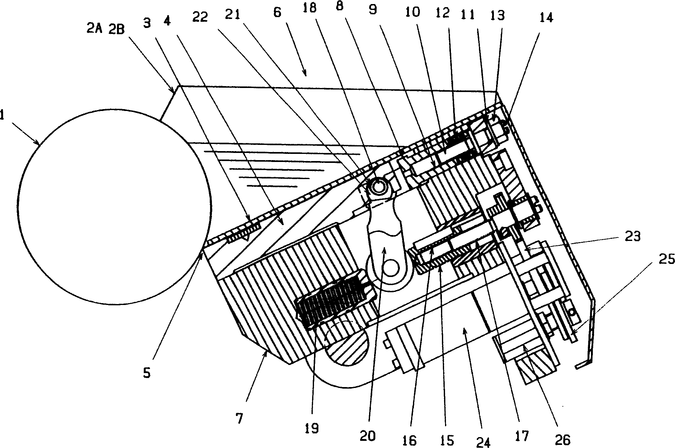
[0026] exist figure 1 Among them, the front face of the rotating ink cartridge represented by reference numeral 6 is surrounded by ink main roller 1, its left and right sides are surrounded by a pair of ink weirs 2A, 2B, and its rear and bottom are surrounded by inclined bottom panel 3.

[0027] In addition, a plurality of ink keys 4 are provided on the bottom side of the bottom panel 3, and these ink keys 4 traverse in a state of being in close contact with the front edge of the bottom panel 3. With the rotation of the main ink roller 1, the ink flows from the main ink roller The gap between ink key 1 and ink key 4, that is, the ink delivery slit t, continuously flows out, and approaches and separates toward the outer peripheral surface of ink main roller 1, and then is in a state of being in contact with it. On the bottom side of these ink keys 4 , there is pr...


PUM


Abstract

An ink cartridge assembly for a printer, which comprises a fulcrum holder (7) arranged behind each ink key (4); a female thread (8) provided at the rear end of the fulcrum holder (7); a screw rod for zero point adjustment ( 9), with a manual rotary operation part; flange (10), which supports the screw rod (9); spring (11), to be crimped on the front end of the fulcrum holder (7) and the rear end surface of the ink key (4) State setting; the moving bushing (15) is located under the front end of the fulcrum holder (7) and can move forward and backward; the female thread (16) is set on the rear end surface of the moving bushing (15); the fine adjustment screw rod (17 ), whose front end is screwed into the female thread (16) and supports the bottom plate (6); the connecting rod (20), which is supported on the front end of the fulcrum holder (7) and behind its floating end to be pressed by the spring (19) It is connected to the front end of the moving bush (15); the center of the eccentric wheel (21) is slightly deviated from the center of the support shaft (18); the semicircular hole (22) is opened in the ink key (4 ) at the rear.

Description

technical field [0001] The invention relates to an ink box assembly of a printer and a control method for an ink key thereof. Background technique [0002] In the past, various printers have been known to control the ink cartridge assembly and its position. For example, the present applicant filed an application for Patent Document 1. pass below Image 6 This known technique will be described. [0003] According to the present invention, the front of the rotating ink cartridge 5 is closed by the ink main roller 1, and its left and right sides are closed by a pair of ink weirs 2A, 2B. Between the front edge of a plurality of ink keys 4 laid in a state of close contact with the bottom side of the ink main roller 1, there is an ink delivery slit t, which is directed towards the outer peripheral surface of the ink main roller 1, so as to realize the movement of advancing and retreating and contacting. state and set. The ink cartridge 5 is installed on the bottom plate portio...

Claims


Application Information

Patent Timeline
Patent Type & Authority Applications(China)
IPC IPC(8): B41F31/04B41F31/02
Inventor 熊木恒夫清水满犬山昭三
Owner JPE
Why Eureka
Try Eureka