Badge and badge manufacturing device

A technology for manufacturing devices and badges, which is applied in the main field of badges, and can solve the problems of pattern paper manufacturing badges, manufacturing difficulties, damage, etc.

Inactive Publication Date: 2005-10-19
BANDAI CO LTD +1
View PDF0 Cites 9 Cited by
  • Summary
  • Abstract
  • Description
  • Claims
  • Application Information

AI Technical Summary

Problems solved by technology

[0004] In order to fix the wearing mechanism 229 of the above-mentioned conventional badge to the mounting mechanism 260 such as a pair of holes 261 and 261 formed on the above-mentioned inner cover 205, the direction of the mark 215 carried on the badge main body 200a and the direction of wearing on the object to be worn The positional relationship of the wearing mechanism 229 such as the fixed pin is fixed, and there is a problem that the installation position of the wearing mechanism 229 cannot be selected corresponding to the direction of the mark 215
In the above-mentioned conventional badge manufacturing apparatus for manufacturing such conventional badges, when manufacturing the main body 200a, the direction of the mark 215 attached to the badge main body 200a and the installation of the pair of holes 261, 261 formed on the inner cover 205, etc. The positional relationship of the mechanism 260 is often inappropriate [for example, the position of the mounting mechanism 260 is inclined relative to the direction of the sign 215, etc., see Figure 19 (c)], in this case, the position of the wearing mechanism 229 installed on the mounting mechanism 260 is also inappropriate for the direction of the sign 215, and when the wearing mechanism 229 is used to wear it on the object to be worn, the direction of the sign 215 is inappropriate. Therefore, the badge main body 200a must be manufactured while confirming the positional relationship between the direction of the mark 215 and the installation mechanism 260, so there is a problem that it is difficult and cumbersome to manufacture the badge main body 200a.
In addition, existing badges still have the problem of being unable to determine the wearing mechanism 229 installed on the badge main body 200a, and choose one of several wearing mechanisms to install.
[0005] Due to the strength problem of the above-mentioned existing badge manufacturing device, each component such as the console and the arm is formed by casting, so there are problems such as heavy weight and high price.
And the depressive force of arm must be quite big, because this depressive force is applied on the control platform, so if the placement position of control platform is unstable, then can not carry out operation, if carry out operation with unstable work platform, will from There is also the possibility of damage if the workbench slips and falls
In the existing badge manufacturing equipment, there is a problem that it is difficult to manufacture badges while confirming the direction of the design paper attached to the front cover and the positions of the pair of holes formed on the back cover.
Therefore, when the fixing pin is installed in a pair of holes, a badge in which the positional relationship between the fixing pin and the design paper is not suitable will be produced.

Method used


Image

  • Badge and badge manufacturing device
  • Badge and badge manufacturing device
  • Badge and badge manufacturing device

Examples


Embodiment Construction

[0094] according to Figure 11 ~ Figure 20 An embodiment of the badge of the present invention will be described. The badge 200 includes a badge body 200a and wearing mechanisms 229, 237, 246, wherein the badge body is made up of: a bezel having a substantially circular face plate 202 and a cover periphery 203 extending downward from the face plate 202 cover 201; sheet body 213 placed on the surface plate 202 of the above-mentioned surface cover 201; an inner cover 205 having a substantially circular inner plate 206 and an inner cover peripheral edge 209 extending upward from the inner plate 206; the inner cover 205 Embedded on the above-mentioned watch cover 201 in this way, that is, the peripheral edge of the above-mentioned sheet body 213 is clamped between the inner cover peripheral edge 209 and the watch cover peripheral edge 203 , so that the above-mentioned sheet body 213 is in close contact with the surface plate 202 . The wearing mechanism is the wearing mechanism 22...


PUM


Abstract

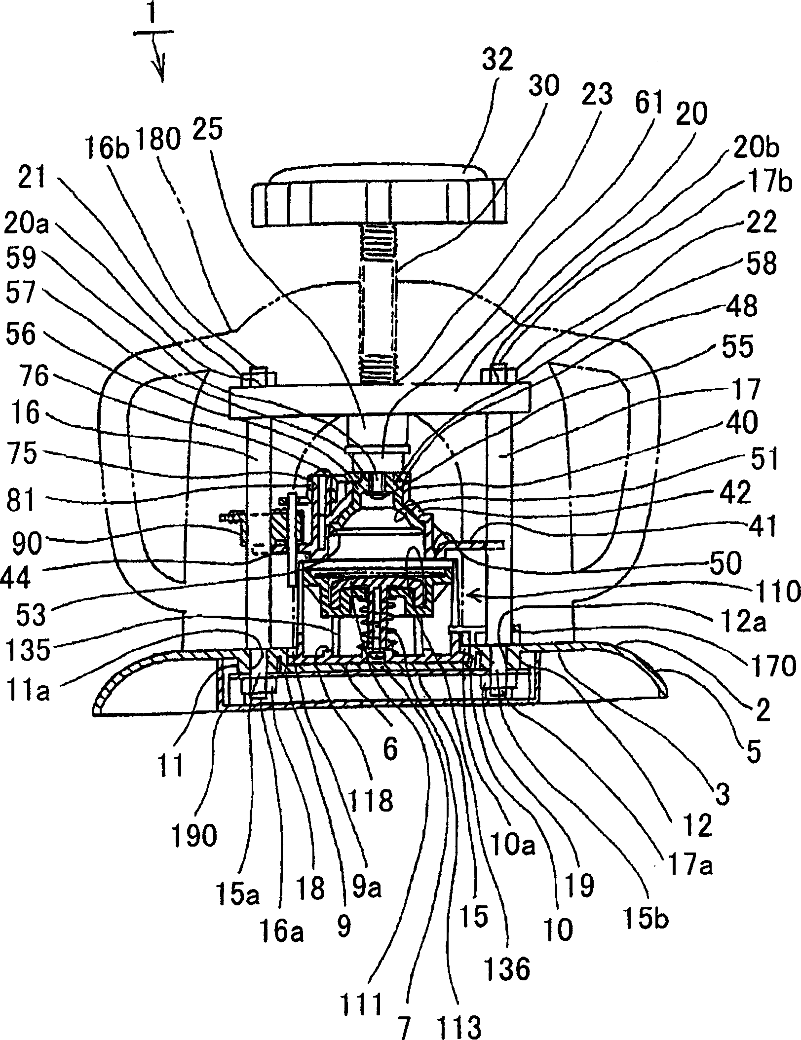
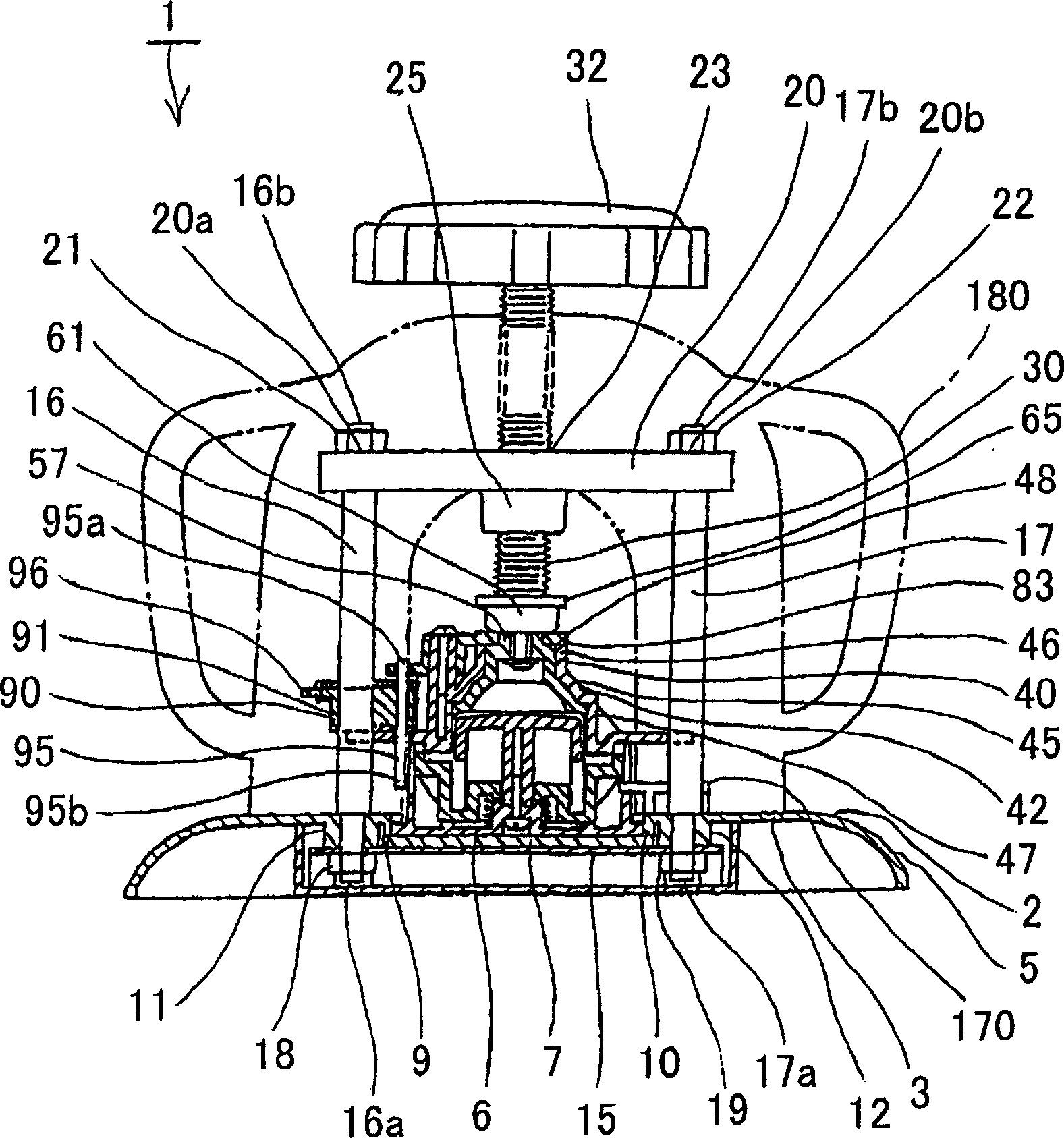
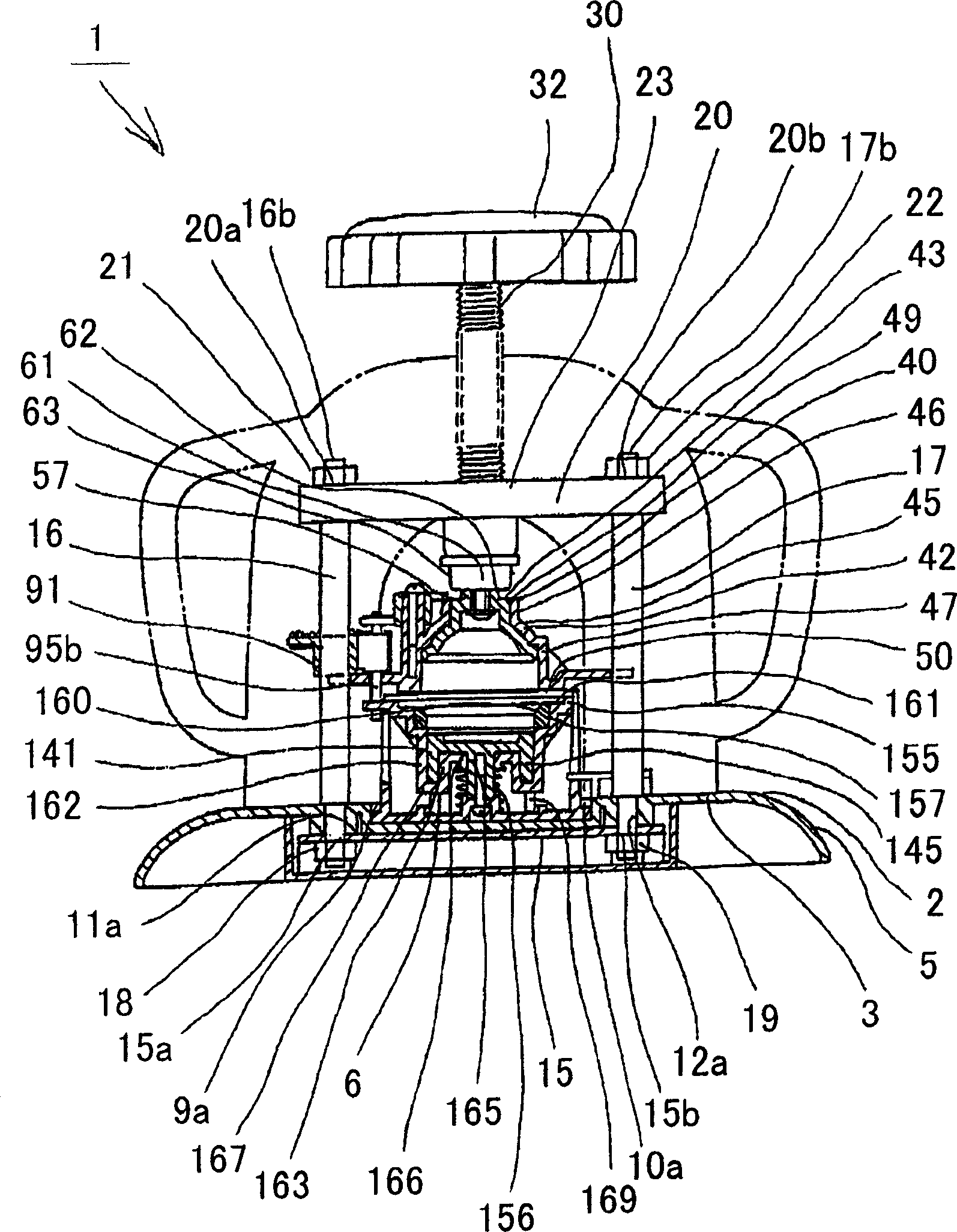
The present invention relates to a badge where it is possible to select the attachment position of attachment means such as a detachable pin while confirming an orientation of an insignia applied to a badge body, and a badge manufacturing device that is lightweight and robust, and that can be operated even at an unstable location and in a small space. A badge 200 comprises a badge body 200a having a front cover 201, a sheet member 213 mounted on a front plate 202 of the front cover 201, and a rear cover 205 for engaging with the front cover 201 to sandwich a peripheral edge of the sheet member 213 between the rear cover peripheral edge 209 and the front cover peripheral edge 203, and attachment means 229, 237 for linking to the badge body 200a by selecting a direction to cross the rear plate 206 of the badge body 200a (X direction, Y direction or Z direction). A badge manufacturing device 1 comprises a base 2, a slide platform 100 provided on the base to be capable of reciprocating movement, first and second lower dies 110 and 140 provided on both sides of the slide platform 100 in the reciprocating directions, a press screw shaft 30 capable of moving in the axial direction by screwing into a female screw section provided on a beam 20 fixed to the upper part of the base via struts 16 and 17, a upper die 40 provided on a lower end of the press screw shaft 30 for joining to the first lower die 110 or the second lower die 140, and an operating handle 32 provided on an upper part of the press screw shaft 30.

Description

technical field [0001] The present invention relates to a badge and a badge manufacturing device having a badge main body with symbols such as characters, patterns, patterns, etc., and a wearing mechanism such as a fixed pin that can be worn on clothes, hats and other worn objects. Background technique [0002] Existing badges such as Figure 21 (a), Figure 21 As shown in (b), it consists of a badge main body 200a with symbols 215 such as characters, designs, patterns, and a wearing mechanism 229 such as a fixed pin that can be worn on clothes, hats and other worn objects. The badge main body 200a is composed of an inner cover 205 and a front cover 201, and is formed in such a way that the design paper 211 provided on the top cover 201 and the transparent cover (sheet) 213 are surrounded by the cover 201. The peripheral edge 203 and the peripheral edge 209 of the inner cover 205 are sandwiched. Symbols 215 such as characters, designs, patterns, etc. are printed on the desi...

Claims


Application Information

Patent Timeline
Patent Type & Authority Applications(China)
IPC IPC(8): A44C3/00A44C27/00
Inventor 金子健児小岛香织菊地宪悦小川岩吉
Owner BANDAI CO LTD
Why Eureka
Try Eureka