
Ink jetting head cleaning device

An inkjet head, cleaning technology, applied in printing and other directions, can solve the problems of light-emitting panel defects, irregularities, and shortening the life of inkjet heads.

Inactive Publication Date: 2005-11-02
RITDISPLAY
View PDF0 Cites 13 Cited by
  • Summary
  • Abstract
  • Description
  • Claims
  • Application Information

AI Technical Summary

Problems solved by technology

[0003] However, the organic electroluminescent element is manufactured by the inkjet method, because the ink used in inkjet printing is usually composed of resin, colorant, electrolyte and mixed solvent. Generally, when the inkjet device is stopped, the ink remaining in the inkjet head must be removed. Ink removal to prevent ink from drying and clogging the nozzles, resulting in ink droplets that cannot be ejected or ink droplets that are uneven, resulting in partial pixels that cannot be filled or irregular, causing defects in the manufactured light-emitting panel, and reducing the life of the inkjet head
At present, the general cleaning of the inkjet head is mainly to use solvent to flush the nozzle of the inkjet head, but in actual operation, when the inkjet head is flushed with the solvent at the solvent end, the ink at the ink inlet end will still flow into the inkjet head. If it is not used for a long time, it will cause the nozzle to clog
And if the solvent is connected to the ink end to rinse the inkjet head instead, it still needs a large amount of solvent to clean the inkjet head, and the consumption of solvent is large
Moreover, when the ink end is connected to the ink pipeline again, the ink concentration will also change due to the presence of solvent in the pipeline.
In addition, if both the solvent end and the ink inlet end are connected to solvent flushing, a large amount of solvent will be wasted, which is not practical in the actual manufacturing process. Therefore, it is urgent to improve the method or device to solve the problem of simplifying the manufacturing process.

Method used


Image

  • Ink jetting head cleaning device
  • Ink jetting head cleaning device
  • Ink jetting head cleaning device

Examples


Embodiment Construction

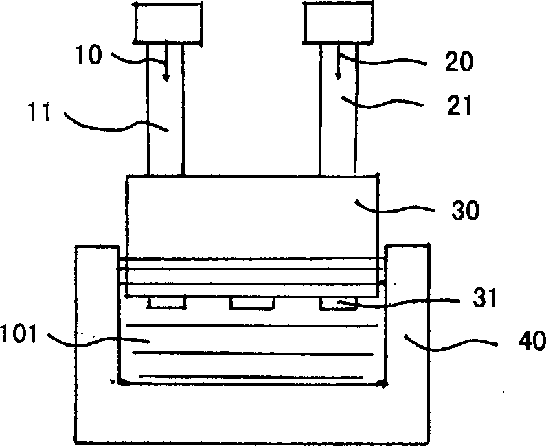
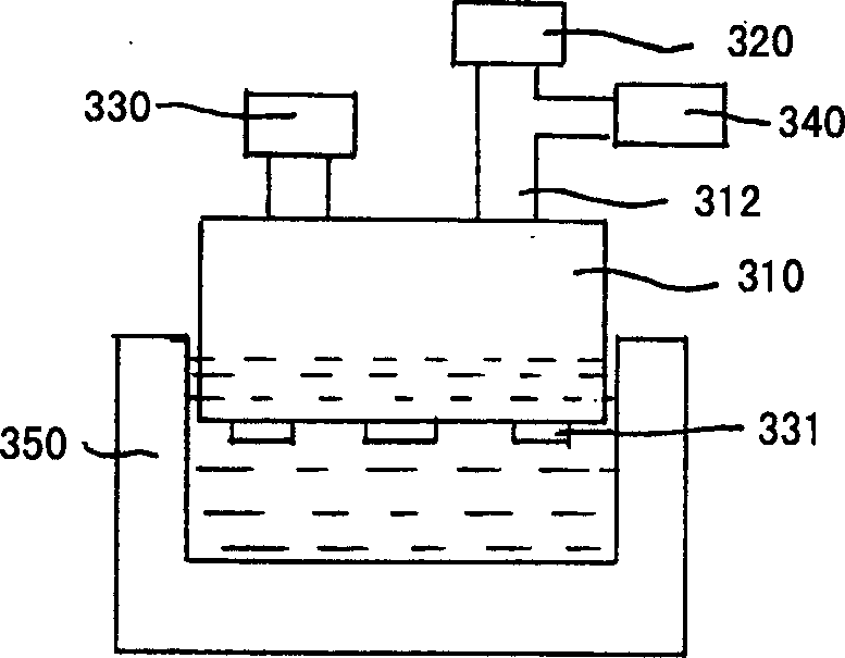
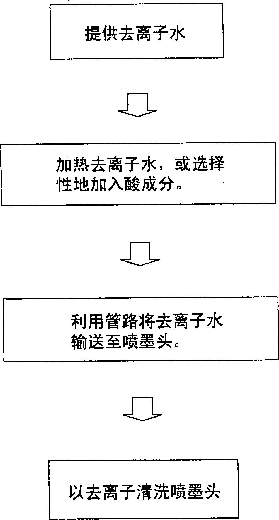
[0032] Cleaning the inkjet head of the present invention preferably further includes providing a container for recovering the used heating solution or weak acid solution; more preferably cleaning the inkjet head further includes providing a storage tank for accommodating the heating solution or weak acid solution. In the device for cleaning the inkjet head of the present invention or in the cleaning inkjet head of the present invention, when the solvent is a weak acid solution or a hot solution with a temperature higher than 20°C, the temperature of the heating solution used is not limited, and can be adjusted at 25 to 65°C as required between ℃. In cleaning the inkjet head of the present invention, the heating solution used is preferably deionized water. In the device for cleaning the inkjet head of the present invention or the weak acid solution used for cleaning the inkjet head of the present invention, the type of acid component is not limited, it can be any component that...


PUM


Abstract

The ink jet head cleaning device for reducing or avoiding ink jet jamming and ink concentration change and reducing consumption of solvent and ink has simplified making process and lowered production cost. The ink jet head cleaning device includes one ink jet head with at least one nozzle and several holes; one multiple joint duct with at least one joint connected to the holes in the ink jet head; one ink supplying element; one solvent supplying element; and one gas supplying element connected to the ink jet head through the multiple joint duct to provide gas to the inside of the ink jet head to eliminate residual ink or solvent, with the gas supplying element being connected with one joint of the multiple joint duct.

Description

technical field [0001] The present invention relates to a device for cleaning an ink-jet head, especially a device suitable for removing residues in the ink-jet head. Background technique [0002] One of the mainstream technologies for manufacturing organic electroluminescent devices is to use inkjet printing to form organic electroluminescent layers (including small molecule organic electroluminescent layers and polymer organic electroluminescent layers). Inkjet printing is a printing method that uses pressure to eject ink from ink nozzles onto the surface of a substrate (such as an organic electroluminescence panel). There are many advantages of manufacturing organic electroluminescent elements by inkjet method. For example, there is no need to use a photomask or a screen, and only a single step is required to print the organic electroluminescent layer into any desired pattern, such as letters, numbers, rules, etc. Or irregular graphics, so its manufacturing process is si...

Claims


Application Information

Patent Timeline
IPC IPC(8): B41J2/165
Inventor 萧夏彩韩于凯
Owner RITDISPLAY
Learn More