Apparatus for removing developer

A developing solution and removal technology, which is applied in the direction of diffusion developing equipment, exposure device for photo-plate making process, photography, etc., can solve the problems of slow operation speed and low safety, reduce the probability of fragmentation, improve safety and save The effect of operating time

Inactive Publication Date: 2005-11-02
HONG FU JIN PRECISION IND (SHENZHEN) CO LTD +1
View PDF0 Cites 3 Cited by
  • Summary
  • Abstract
  • Description
  • Claims
  • Application Information

AI Technical Summary

Problems solved by technology

[0006] In order to overcome the defects of low safety and slow operation speed of the prior art developer remo

Method used


Image

  • Apparatus for removing developer
  • Apparatus for removing developer
  • Apparatus for removing developer

Examples


Embodiment Construction

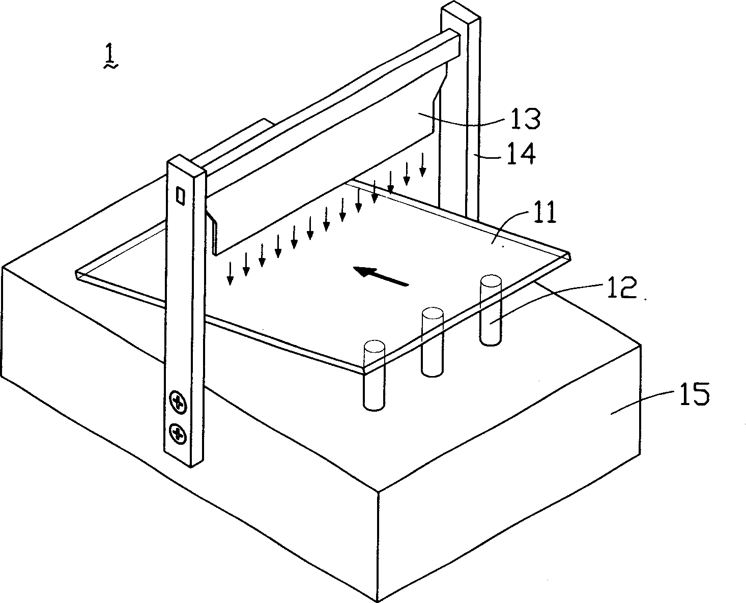
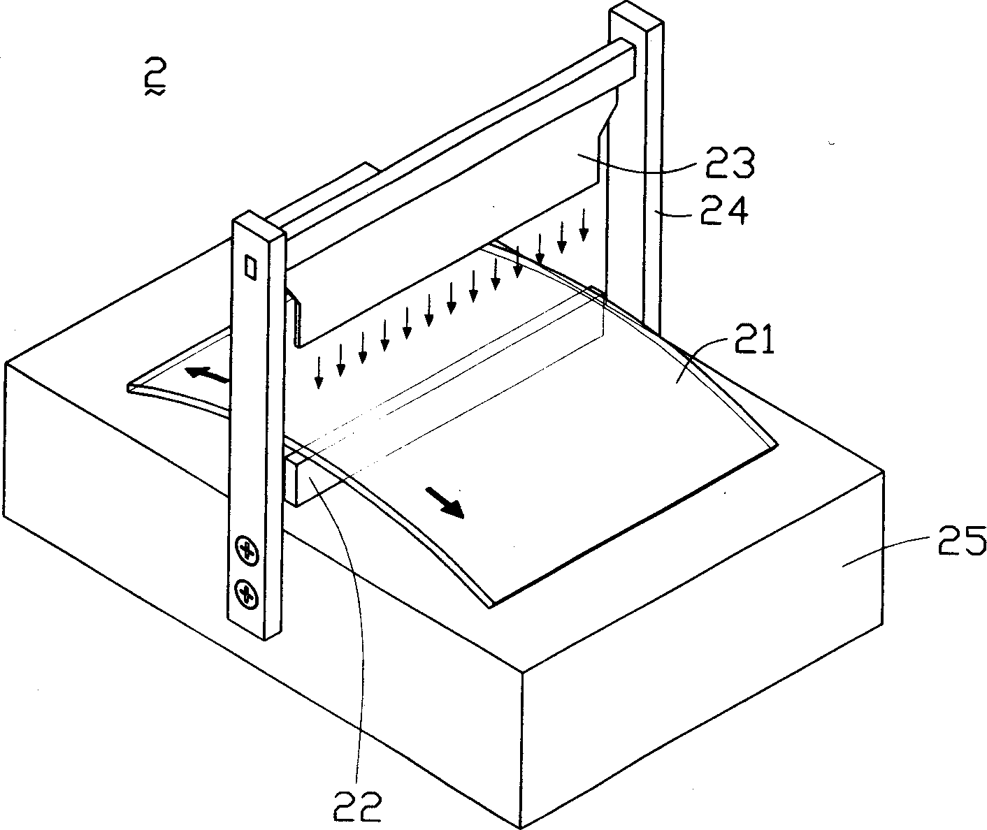
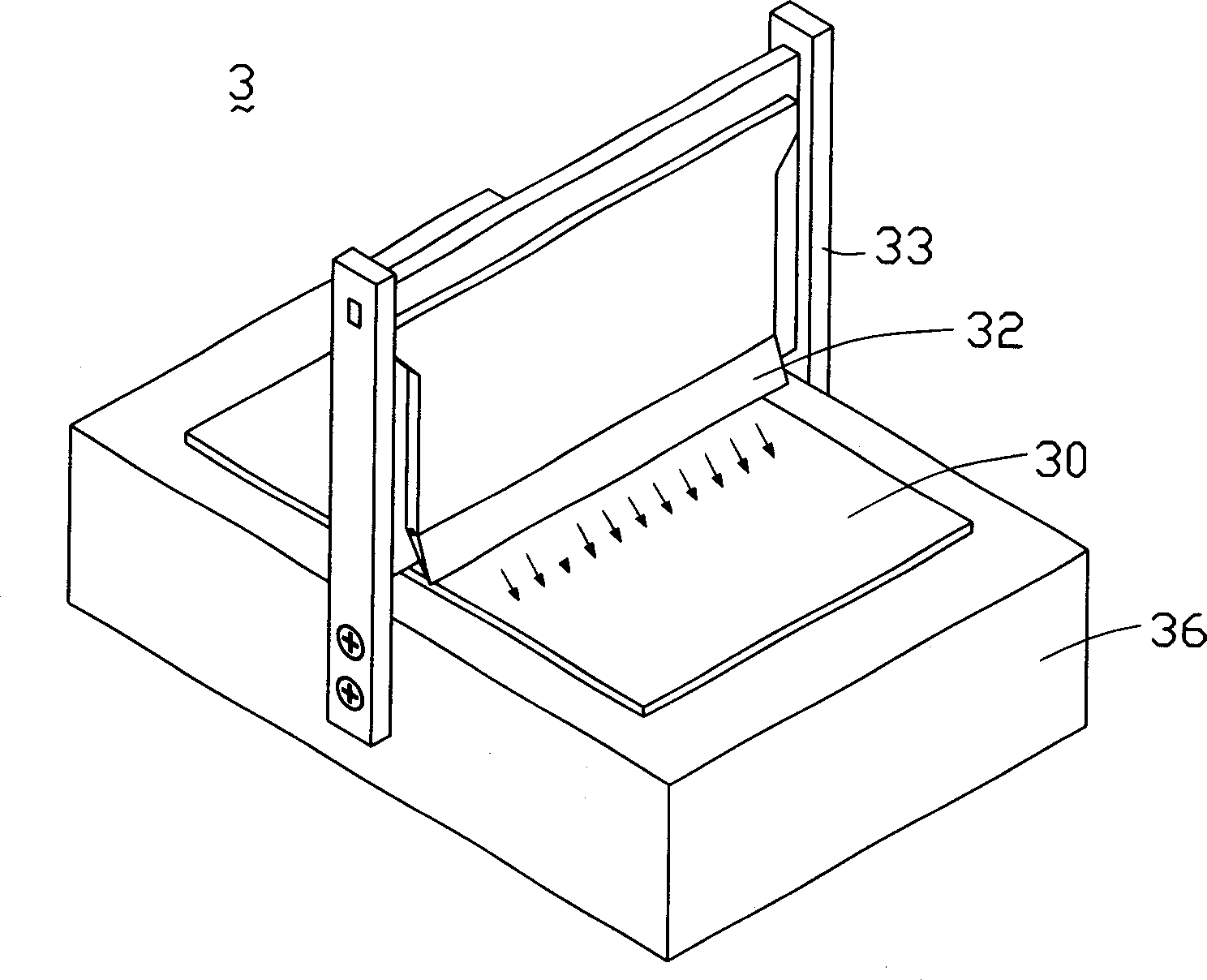
[0013] Please refer to image 3 with Figure 4 , image 3 Is a perspective view of the first embodiment of the developer removing device of the present invention, Figure 4 It is a plan view of the first embodiment of the developer removing device of the present invention. The developer removal device 3 of the present invention includes a workbench 36, a support 33, a nozzle support bridge 37, a gas nozzle 31, and a deionized water nozzle 32. The workbench 36 is used to carry the substrate 30. The support 33 is fixed on the workbench 36, and the nozzle support bridge 34 is fixed on the support 33. The gas nozzle 31 and the ionized water nozzle 32 are respectively located on both sides of the nozzle support bridge 34. In addition, the gas nozzle 31 and the ionized water nozzle 32 are connected to the nozzle support bridge 37 through the hubs 34 and 35, respectively, so that the gas nozzle 31 and the ionized water nozzle 32 can spray gas and deionized water to the substrate at differe...


PUM


Abstract

The invention discloses developing solution movement device, which comprises a workbench to support basal plate and a bracket; wherein, set deionized water nozzle and a gas nozzle on the bracket, the two nozzles connect separated to two hinges. This device can clear away developing solution on surface of basal plate quickly and safety.

Description

【Technical Field】 [0001] The invention relates to a developing process equipment, in particular to a developing solution removing device. 【Background technique】 [0002] The lithography process is mainly composed of photoresist coating, exposure and development. The coating process is to uniformly coat the photoresist on the surface of the substrate; the exposure process is to transfer the pattern on the photoresist to the photoresist by using the photosensitive characteristics of the photoresist; the development process is to use a developer to remove unnecessary photoresist, Make the graphics appear on the substrate completely. [0003] As far as the development process is concerned, the Thin Film Transistor (TFT) industry generally uses the relative movement between the glass and the developer nozzle to achieve the developer coating on the surface of the glass substrate, and then let it stand for a period of time until the reaction is completed. After that, the developer on th...

Claims


Application Information

Patent Timeline
IPC IPC(8): G03D5/04G03D9/00G03F7/00G03F7/20G03F7/30G03F7/32
CPCG03F7/0007G03F7/30G03D5/04G03F7/322G03F7/32
Inventor 许文诚王敬龙詹育颖曾增魁
Owner HONG FU JIN PRECISION IND (SHENZHEN) CO LTD
Why Eureka
Try Eureka