
Semiconductor light emitting device and fabrication method thereof

A technology for light-emitting devices and semiconductors, applied to semiconductor devices, electrical solid-state devices, electrical components, etc., can solve problems such as no record of lead frames, and achieve the effects of reducing unevenness, reducing size, and improving heat dissipation

Active Publication Date: 2005-11-02
SHARP KK
View PDF4 Cites 12 Cited by
  • Summary
  • Abstract
  • Description
  • Claims
  • Application Information

AI Technical Summary

Problems solved by technology

As a result, there are cases where size reduction of the light-emitting element is limited
Note that the third conventional example does not document the concept of using a leadframe

Method used


Image

  • Semiconductor light emitting device and fabrication method thereof
  • Semiconductor light emitting device and fabrication method thereof
  • Semiconductor light emitting device and fabrication method thereof

Examples


Embodiment Construction

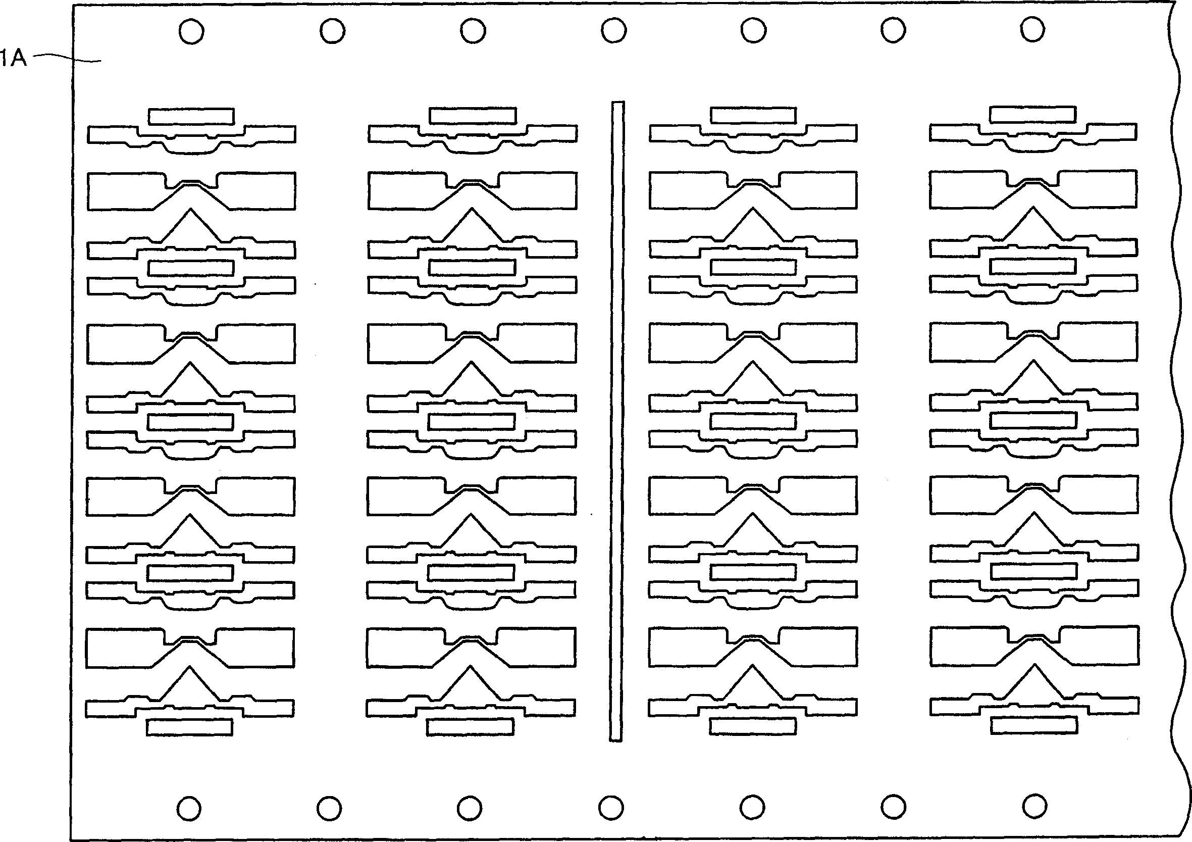
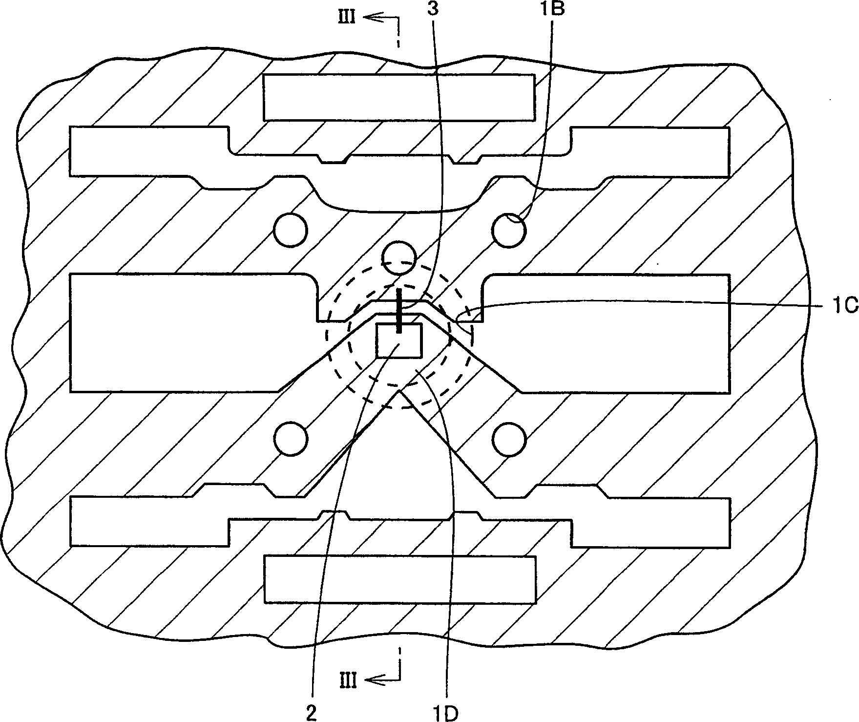
[0037] The following will refer to Figure 1-6 Embodiments of the semiconductor light emitting device and its manufacturing method according to the present invention will be described.

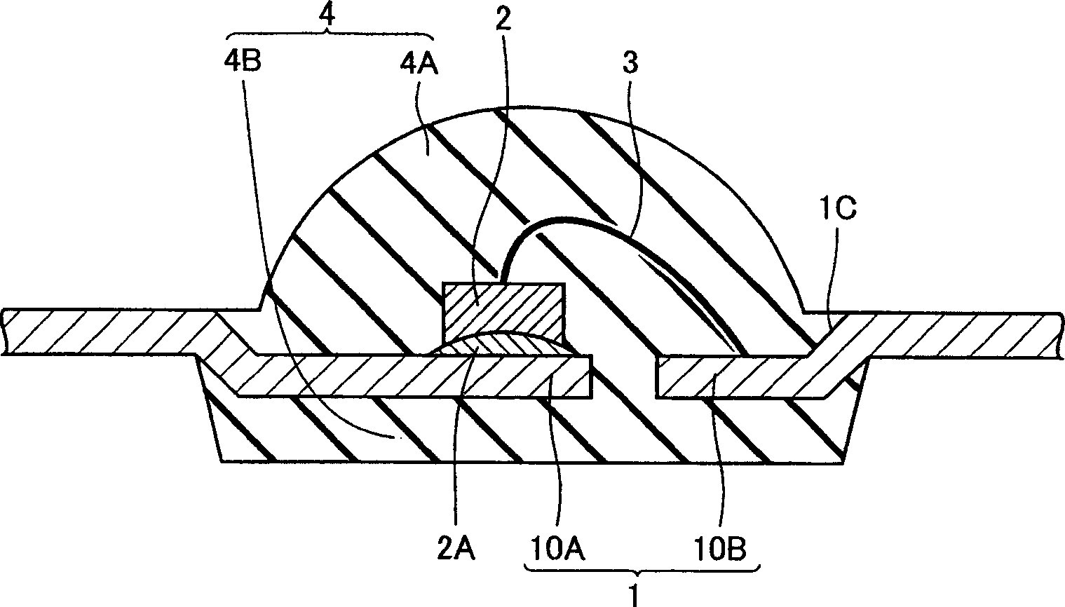
[0038] refer to Figure 5 , the semiconductor light emitting device according to the embodiment of the present invention includes: LED element 2 (semiconductor light emitting element); lead frame 10A (first lead frame) on which LED element 2 is mounted; lead wires electrically connected to LED element 2 through wiring 3 Frame 10B (second lead frame); transparent resin 4 (light-transmitting resin) formed on LED element 2 and lead frame 1 (10A, 10B); and light-shielding resin 7 (blocking resin) Light resin), and surround the periphery of the LED element 2. The transparent resin 4 includes a lens portion 4 and a holding portion 4B holding the lead frame 1 , wherein the lens portion 4A constitutes a lens on the LED 2 .

[0039] The front end of lead frame 1 is inserted into transparent resin 4 ...


PUM


Abstract

A semiconductor light emitting device includes an LED element, a lead frame on which the LED is mounted, a lead frame electrically connected to the LED element via a wire, transparent resin formed on the LED element and on the lead frames, and light shielding resin having a reflectance higher than the reflectance of the transparent resin, surrounding the perimeter of the LED. The transparent resin includes a lens portion constituting a lens on the LED, and a holding portion holding the lead frame.

Description

[0001] This is a non-provisional application based on Japanese Patent Application No. 2004-131774 filed with the Japan Patent Office on April 27, 2004, the contents of which are hereby incorporated by reference in their entirety. technical field [0002] The invention relates to a semiconductor light emitting device and a method for manufacturing the semiconductor light emitting device. Specifically, the present invention relates to a semiconductor light emitting device using a light emitting element such as an LED (Light Emitting Diode), and a method of manufacturing such a semiconductor light emitting device. Background technique [0003] Semiconductor light emitting devices generally using light emitting elements such as LEDs are known. [0004] For example, Japanese Patent Laid-Open No. 11-087789 (First Conventional Example) discloses a light emitting device including: a light emitting element on which a lead frame of the light emitting element is mounted for electrical ...

Claims


Application Information

Patent Timeline
Patent Type & Authority Applications(China)
IPC IPC(8): H01L29/22H01L33/54H01L33/56H01L33/62
CPCH01L2224/32245H01L33/62H01L2224/48091H01L24/97H01L33/54H01L2224/73265H01L2224/48247H01L2924/12041H01L2924/01004H01L2924/3025H01L33/647H01L33/486H01L2224/97H01L2924/181H01L2924/00014H01L2924/00H01L2924/00012
Inventor 阿部宗造吉田智彦
Owner SHARP KK
Learn More