Optical modulation device holding body, optical device, and projector

A technology of light modulation device and optical device, applied in optics, projection device, image reproducer using projection device, etc., can solve the problem that the polarizing plate cannot be set to a specified position, the polarizing plate cannot be replaced, and it is difficult to adjust the position of the polarizing plate. and other problems, to achieve the effects of easy position adjustment, improved manufacturing efficiency, and reduced position deviation

Inactive Publication Date: 2005-11-02
SEIKO EPSON CORP
View PDF2 Cites 2 Cited by
  • Summary
  • Abstract
  • Description
  • Claims
  • Application Information

AI Technical Summary

Problems solved by technology

[0010] That is, when the polarizing plate is pulled out (peeled off) from the cross dichroic prism, the adhesive or the like remains on the cross dichroic prism, making it difficult to install a new polarizing plate on the cross dichroic prism and reposition it. Adjustment
[0011] In addition, the polarizing plate cannot be installed at the specified position due to adhesive residue etc. fixed on the cross dichroic prism.
[0012] In addition, since the polarizing plate is interposed between the light modulating device and the cross dichroic prism, when the polarizing plate is pulled out from the cross dichroic prism, the light modulating device must also be removed, and only the polarizing plate cannot be replaced.

Method used


Image

  • Optical modulation device holding body, optical device, and projector
  • Optical modulation device holding body, optical device, and projector
  • Optical modulation device holding body, optical device, and projector

Examples


Embodiment Construction

[0068] Embodiments of the present invention will be described below with reference to the drawings.

[0069] (1) Appearance structure

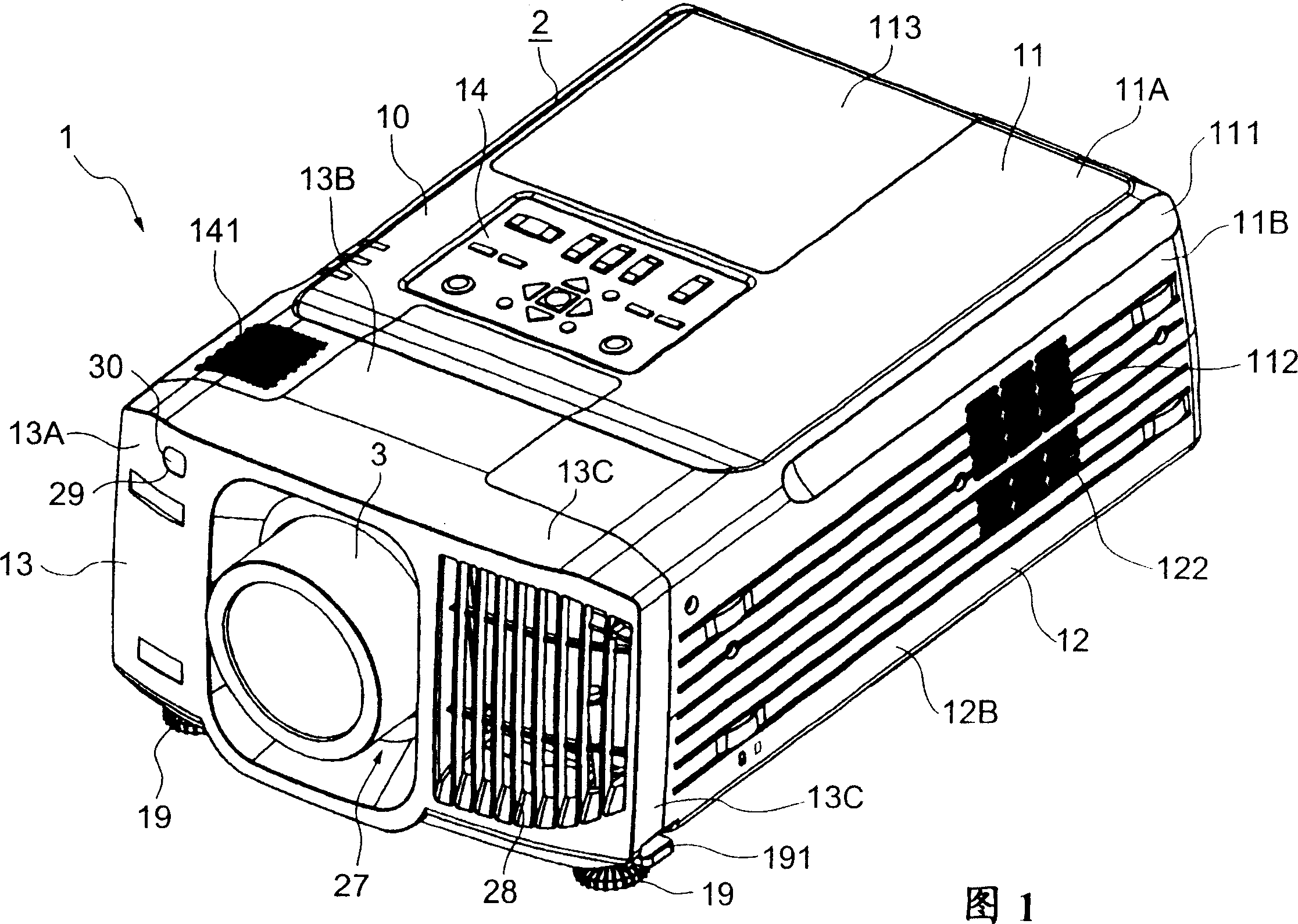
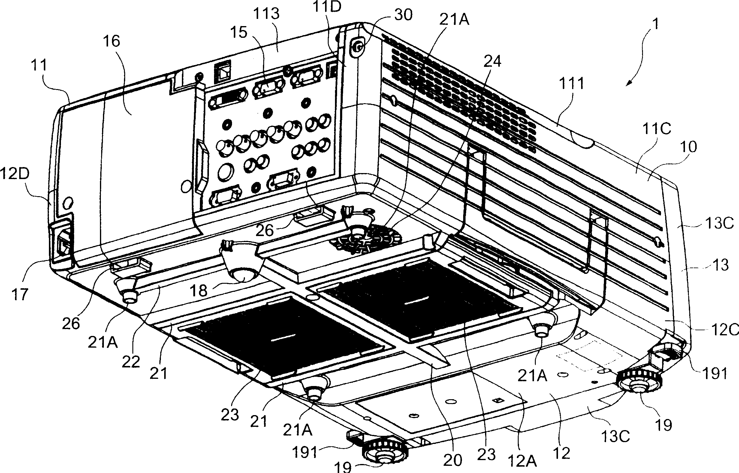
[0070] Figure 1 and figure 2 Showing a projector 1 according to an embodiment of the present invention, FIG. 1 is a perspective view viewed from the upper front side, figure 2 It is a perspective view seen from the lower back side.

[0071] The projector 1 is an optical device that modulates a light beam emitted from a light source according to image information and projects it on a projection surface such as a screen in a magnified manner. 2 and a projection lens (lens) 3 exposed from the exterior case 2 as a projection optical system. This projector 1 is installed in a large store or a public place, etc., and displays a projected image on a large screen to provide image information to a plurality of observers.

[0072] The projection lens 3 has the function of a projection optical system for enlarging and projecting an optical image form...


PUM


Abstract

An optical modulator holder, optical device and projector are capable of easily replacing an optical modulator and / or optical transducing element, increasing reworkability. A panel fixing plate (446) serving as the optical modulator holder comprises a fixing section main body (4461) substantially C-shaped as seen in a plan view, an arm (4462) formed at the front end of the fixing section main body (4461), pins (4463) projecting from the arm (4462), and spring members (4465) urging an emission-side polarizing plate (444), which serves as an optical transducing element, against the fixing section main body (4461). Liquid crystal panels (441R, 441G, 441B) serving as an optical modulator are held and fixed by the panel fixing plate (446) by passing the pins (4463) through holes (4413). Further, the emission-side polarizing plate (444) is inserted in the fixing section main body (4461), which is substantially C-shaped as seen in a plan view, and is urged by the spring members (4465) to be fixed in the fixing section main body (4461).

Description

technical field [0001] The present invention relates to a holder for holding a light modulating device for modulating color light according to image information, an optical device and a projector. Background technique [0002] So far, there are known a plurality of light modulation devices for modulating a plurality of color lights for each color light according to image information, a color synthesis optical device for combining the modulated color lights to form an optical image, and a projection lens for enlarging and projecting the formed optical image. Projector. [0003] In a projector, a color separation optical system such as a dichroic mirror separates a light beam emitted from a light source into three colors of light. In addition, three light modulators composed of a liquid crystal panel etc. modulate each color light according to image information. In addition, a color synthesizing optical device such as a cross dichroic prism synthesizes the modulated light of...

Claims


Application Information

Patent Timeline
Patent Type & Authority Applications(China)
IPC IPC(8): H04N5/74H04N9/31
CPCH04N9/3144H04N9/3197H04N9/3141H04N9/3105
Inventor 上原太介
Owner SEIKO EPSON CORP
Why Eureka
Try Eureka