Backlight module structure

A technology for backlight modules and light-emitting components, which is applied in optics, nonlinear optics, instruments, etc., and can solve problems such as inability to make thinner and larger display panels

Inactive Publication Date: 2005-11-09
AU OPTRONICS CORP
View PDF0 Cites 3 Cited by
  • Summary
  • Abstract
  • Description
  • Claims
  • Application Information

AI Technical Summary

Problems solved by technology

[0013] Moreover, the above-mentioned driving circuit structure is directly integrated into the light-emitting element array. In addition to simplifying the structure of the control circuit, the number of pins connecting the light-emitting ele

Method used


Image

  • Backlight module structure
  • Backlight module structure
  • Backlight module structure

Examples


Embodiment Construction

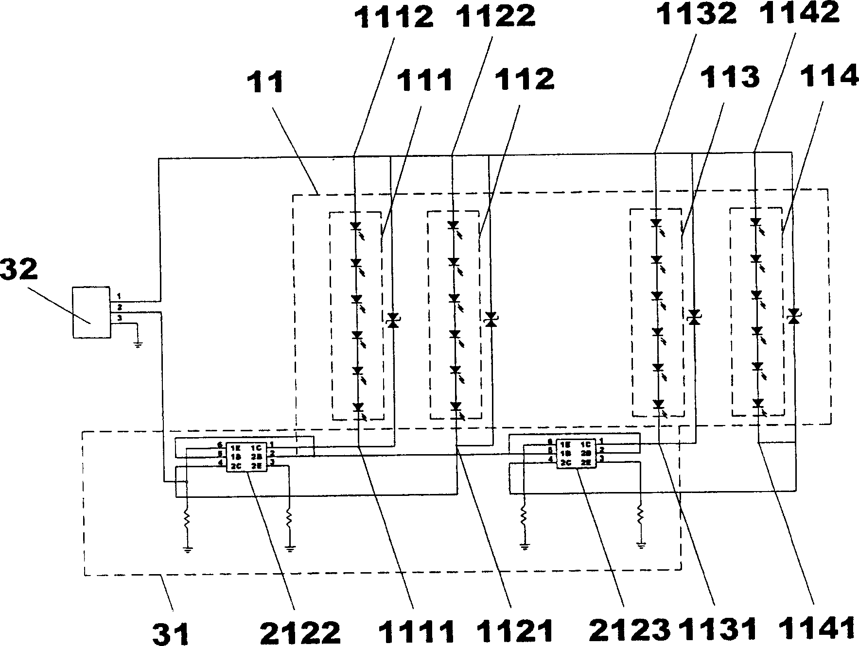
[0048] image 3 It is disclosed that the circuits of the light-emitting component array 11 and its driving circuit structure 31 in the present invention are directly combined. The aforementioned driving circuit structure 31 is composed of two transistor chips 2122 and 2123 . Transistor chip as the known technical number 2122 is used to provide the first series light emitting component 111 and the second series light emitting component 112 by connecting to the first terminal 1111 of the first series light emitting component and the first terminal 1121 of the second series light emitting component The required same current value is used as its control signal connection terminal. In addition, the transistor chip numbered 2123 is connected to the first end 1131 of the third series light emitting element and the first end 1141 of the fourth series light emitting element to provide the third series light emitting element 113 and the fourth series light emitting element 114. The re...


PUM


Abstract

The invention discloses a structure design of a weakening light module used in the flat display device. The design effectively adjusts the array of luminescence parts which belongs to well-known technology and the array control electric circuit unit. In the meanwhile, when the array mentioned above is linked with its control electric circuit, the increased quantity of luminescence parts in series is independent of the quantity of feet used for connecting interface units.

Description

technical field [0001] The invention relates to the design of a backlight unit structure, in particular to the design of the connection relationship between a light-emitting array and a control circuit in the backlight unit structure. Background technique [0002] With the increasing size and thinning trend of flat display devices such as liquid crystal screens in the market, the size of the display panel is gradually increasing, which also increases the size of the backlight module, and the array of light-emitting components in its structure needs to be increased. More groups of light-emitting components in series composed of light-emitting components such as light-emitting diodes (Light Emitting Diode, LED). Each group of series-connected light-emitting components is then connected in parallel to form its light-emitting component array. In addition, each group of series-connected light-emitting components needs to provide a power connection pin through a light-emitting co...

Claims


Application Information

Patent Timeline
IPC IPC(8): G02F1/1335G09G3/34G09G3/36
Inventor 刘准任郭旻谦
Owner AU OPTRONICS CORP
Why Eureka
Try Eureka