Beating device for loom

A technology of looms and balance shafts, applied in looms, lighting devices, textiles, etc., can solve problems such as inability to obtain effects, and achieve the effect of reducing weight

Inactive Publication Date: 2005-12-07
TSUDAKOMA KOGYO KK
View PDF0 Cites 9 Cited by
  • Summary
  • Abstract
  • Description
  • Claims
  • Application Information

AI Technical Summary

Problems solved by technology

However, according to the publication of Patent Document 1, the cross-sectional shape of the balance shaft is circular, and the above-mentioned effects cannot be obtained.

Method used


Image

  • Beating device for loom
  • Beating device for loom
  • Beating device for loom

Examples


Embodiment Construction

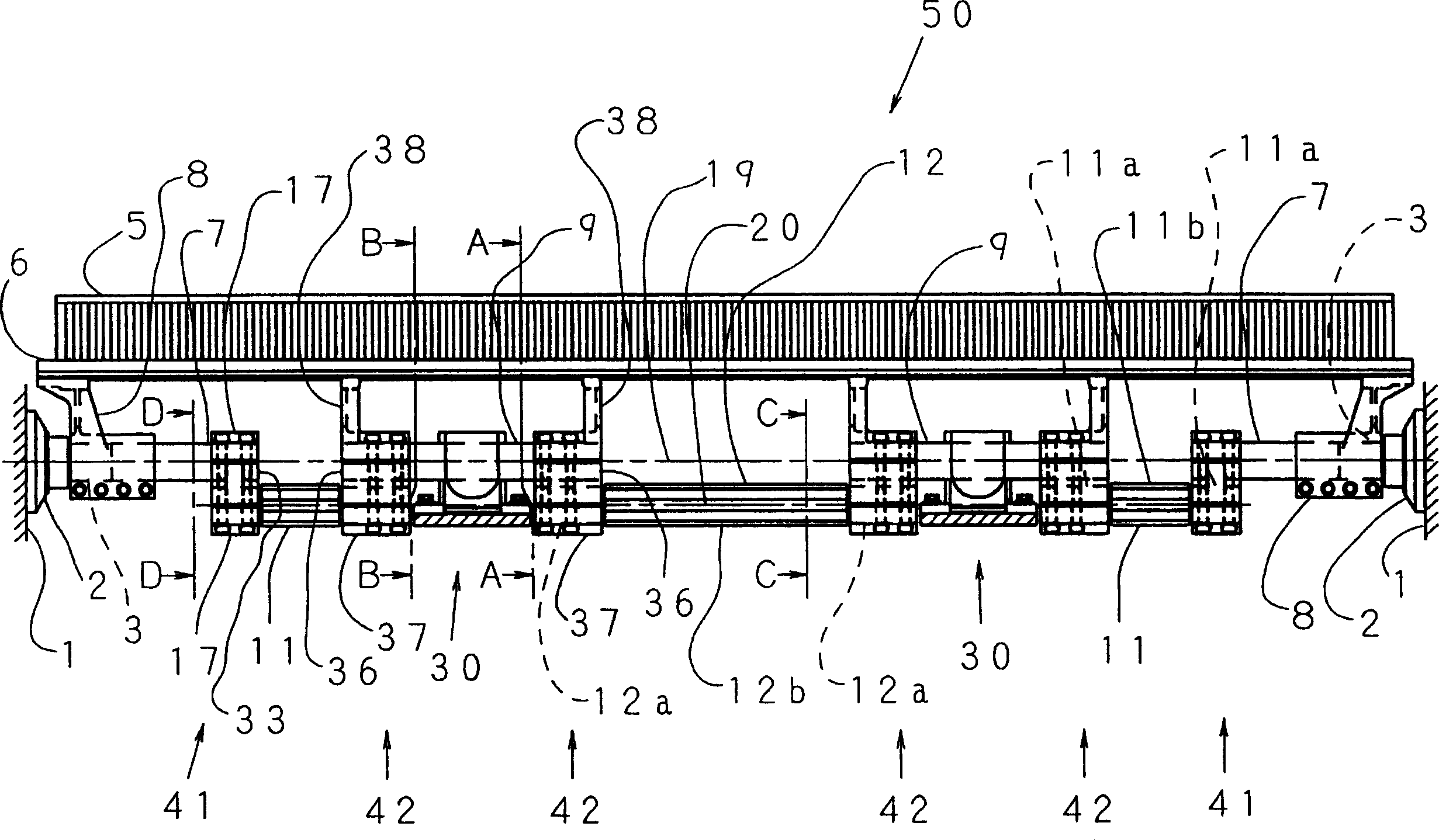
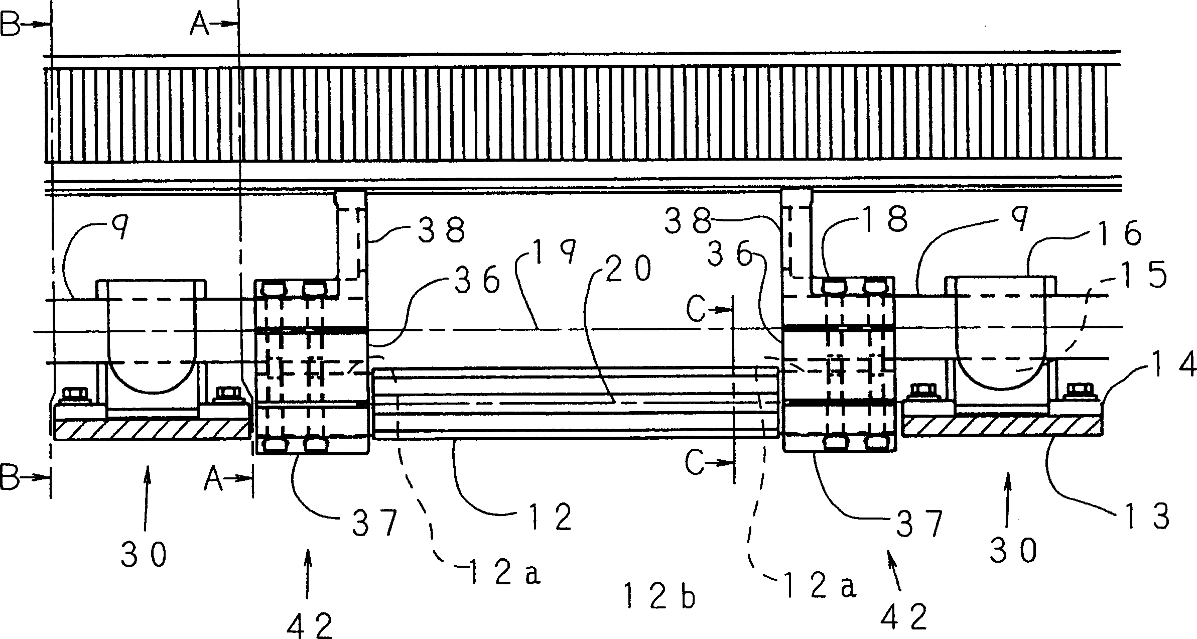
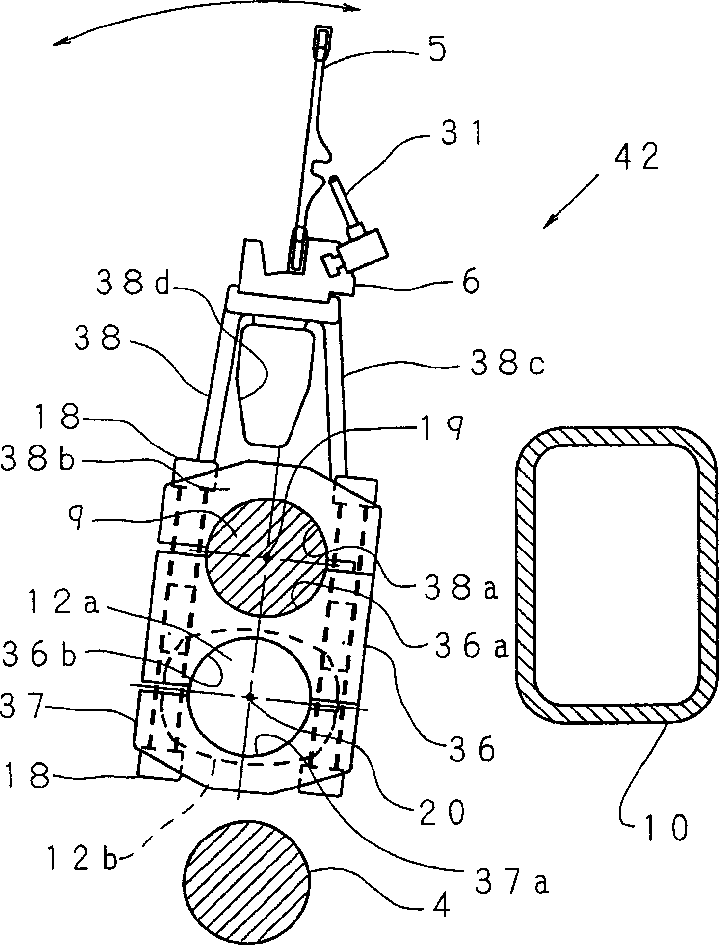
[0031] Hereinafter, embodiments of the present invention will be described with reference to the drawings. Figure 1 ~ Figure 7 Shown is the first embodiment of the present invention on the beating-up device 50 of an air jet loom. figure 1 Is the front view seen from the winding side, figure 2 Yes figure 1 Enlarged view of the main part. image 3 , Figure 4 Yes figure 1 and figure 2 Side view of the A-A section, image 3 Indicates the beat-up state, Figure 4 Indicates that the reed is in the state of the last retreat on the sending side. Figure 5 Yes figure 1 and figure 2 Side view of the B-B section. Figure 6 Yes figure 1 D-D section view. Figure 7 Yes figure 1 and figure 2 C-C section view.

[0032]The beating-up device 50 includes: a pair of end support members 2, 2 respectively provided on the left and right frames 1, 1 of the loom; two first rotatably supported by a pair of end support members 2, 2 respectively Swing shafts 3, 3; a pair of driving devices not sh...


PUM


Abstract

A beating device for a loom includes a plurality of rocking shafts disposed distant from each other in a width direction of cloth to be woven by the loom; a balance shaft disposed farther away from a reed than the rocking shafts and extending in said width direction, the balance shaft being disposed between the neighboring rocking shafts; and a pair of connection units for respectively connecting two opposite ends of the balance shaft with ends of the neighboring rocking shafts. The balance shaft is non-circular in cross-section such that a rocking-direction flexural-rigidity of the balance shaft is greater than a flexural-rigidity of the balance shaft in a direction perpendicular to the rocking direction.

Description

Technical field [0001] The invention relates to a beating-up device of a loom. Background technique [0002] The beating-up device of the loom has: a swing shaft that rotates in conjunction with the rotation of the main shaft of the loom, a plurality of sley feet mounted on the swing shaft, a sley clamp supported by the plurality of sley feet, and a fixed The reed on the reed clip. In this way, the reed, the reed clamp, and the sley foot become a connection with the swing shaft, swing around the swing shaft, and perform beating motion in conjunction with the rotation of the main shaft of the loom. However, the center of gravity of the pendulum shaft and its connected object is closer to the reed side position than the center of swing, and the center of gravity is greatly different from the swing center, that is, the pendulum shaft and its connected object are in an unbalanced state. Therefore, vibrations are generated along with the beating-up motion, and parts wear and noise are...

Claims


Application Information

Patent Timeline
Patent Type & Authority Applications(China)
IPC IPC(8): D03D49/60
CPCD03D49/60F21K9/235F21K9/237F21Y2115/10
Inventor 南谷德生名木启一
Owner TSUDAKOMA KOGYO KK
Why Eureka
Try Eureka