
Fluid actuator

A fluid actuator, actuator technology, applied in the direction of fluid pressure actuators, liquid fuel engines, components of pumping devices for elastic fluids, etc., can solve leakage of actuators, generation of metal debris, wear and tear Sealing components etc.

Inactive Publication Date: 2005-12-07
SWAGELOK CO
View PDF0 Cites 6 Cited by
  • Summary
  • Abstract
  • Description
  • Claims
  • Application Information

AI Technical Summary

Problems solved by technology

The galling action due to metal-to-metal contact can generate metal chips and create a rough surface that wears down the sealing elements, causing leaks or stopping the actuator

Method used


Image

  • Fluid actuator
  • Fluid actuator
  • Fluid actuator

Examples


Embodiment Construction

[0020] Although aspects of the invention are described and illustrated herein in connection with exemplary embodiments, these aspects can also be realized by many alternative embodiments, which can be present alone or in combination and in partial combinations. All such combinations and subcombinations are within the scope of the present invention, unless it is clearly indicated herein that they do not belong thereto. In addition, while various alternative embodiments and features of the invention have been described herein with respect to aspects, such as other alternative materials, structures, configurations, methods, devices, software, hardware, and control logic, etc., these descriptions do not It is not intended to be a complete or exhaustive list of available alternative embodiments, either currently known or hereafter developed. Those skilled in the art can readily incorporate one or more aspects, concepts or features of the present invention into additional embodiment...


PUM


Abstract

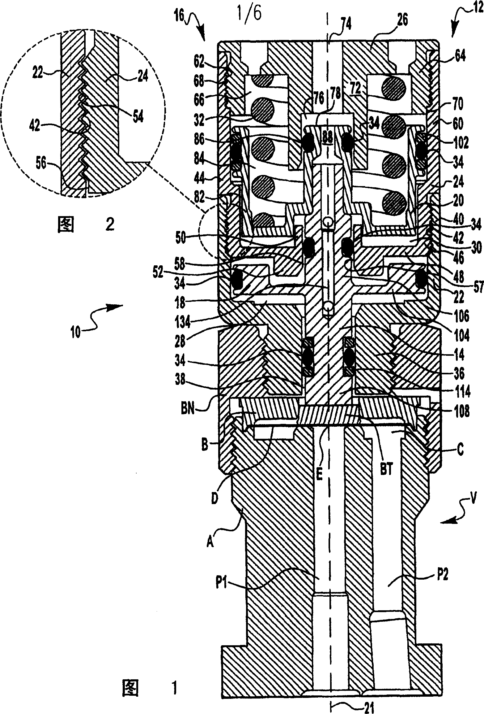
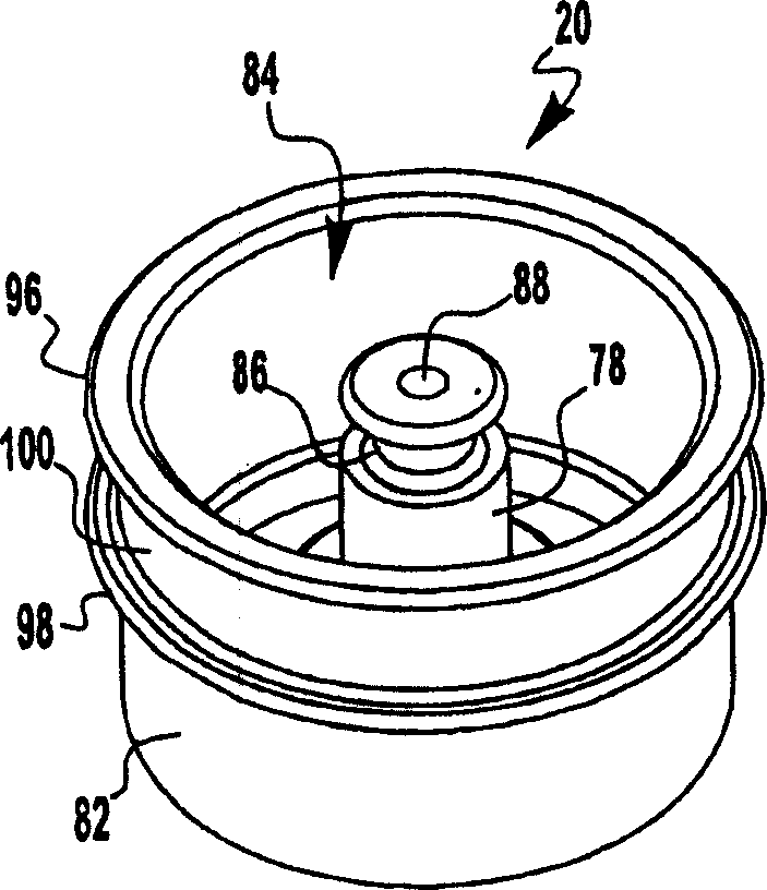
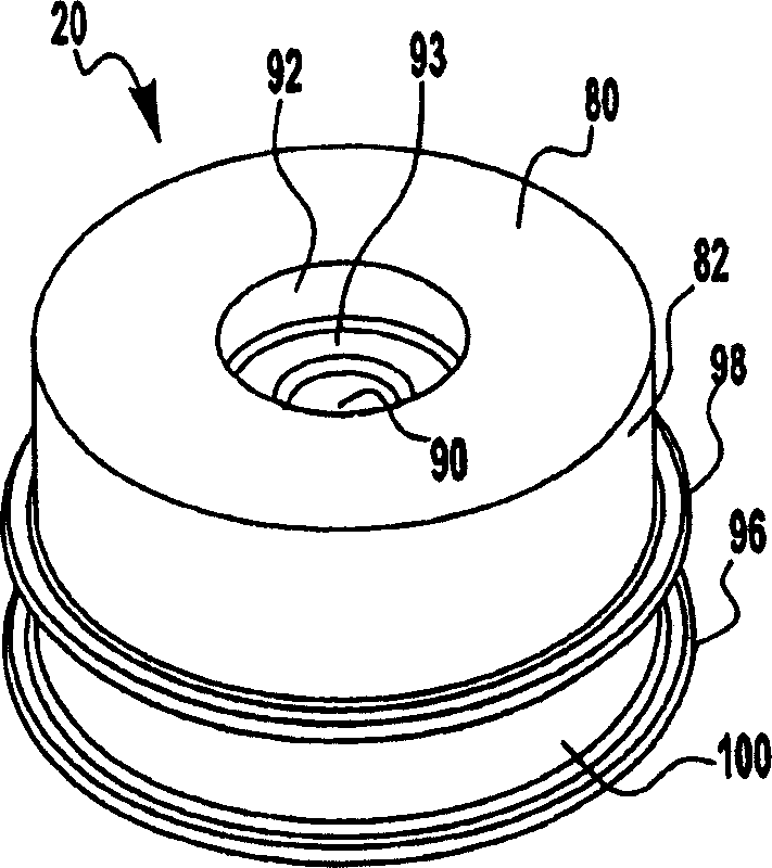
A fluid actuator configured for achieving extended cycle life and reduced overall actuator height. The actuator may include a nesting arrangement between portions of the actuator to reduce overall height and provide stability. The actuator may also join movable members and include a guidance mechanism to avoid undesired contact between actuator portions.

Description

[0001] related application [0002] This application claims priority to U.S. Provisional Patent Application Serial No. 60 / 575,998, filed June 1, 2004, entitled Deep Piston Air Actuator, the entire disclosure of which is hereby incorporated by reference . Background technique [0003] Actuators are used to control the operation of many valves and other components of fluids, which may be liquids, gases, or mixtures thereof. Actuators can come in many different designs, including pneumatic, hydraulic, and electric, to name a few. Piston actuators use pressurized fluid, such as air, to drive a piston to open and / or close a fluid component. The actuator may use multiple pistons to obtain an increased surface area on which the pressurized fluid acts, thereby increasing the output force of the actuator. However, the use of multiple pistons generally increases the overall height of the actuator, which may make such an actuator impractical for certain applications. [0004] Known a...

Claims


Application Information

Patent Timeline
IPC IPC(8): F04B1/00F04B39/00F04B53/14F15B15/14
CPCF04B53/143
Inventor G·谢菲尔J·S·蒂姆科
Owner SWAGELOK CO
Learn More