Lens module fixing arrangement and method

A lens module and fixed structure technology, applied in installation, optics, instruments, etc., can solve the problems of increased manufacturing cost, decreased product mass production, and inability to achieve fixed effects, etc., achieving easy implementation, simple structure, and avoiding the focus position Staggered effect

Inactive Publication Date: 2005-12-07
HONG FU JIN PRECISION IND (SHENZHEN) CO LTD +1
View PDF0 Cites 27 Cited by
  • Summary
  • Abstract
  • Description
  • Claims
  • Application Information

AI Technical Summary

Problems solved by technology

However, the application of this method will cause the following problems: if UV glue (ultraviolet glue, ie ultraviolet glue) is used to dispense glue at the joint, the ultraviolet light cannot be irradiated into the joint between the lens barrel and the lens mount, and the UV glue (ultraviolet glue, ie ultraviolet glue) cannot be applied to the join

Method used


Image

  • Lens module fixing arrangement and method
  • Lens module fixing arrangement and method
  • Lens module fixing arrangement and method

Examples


Embodiment Construction

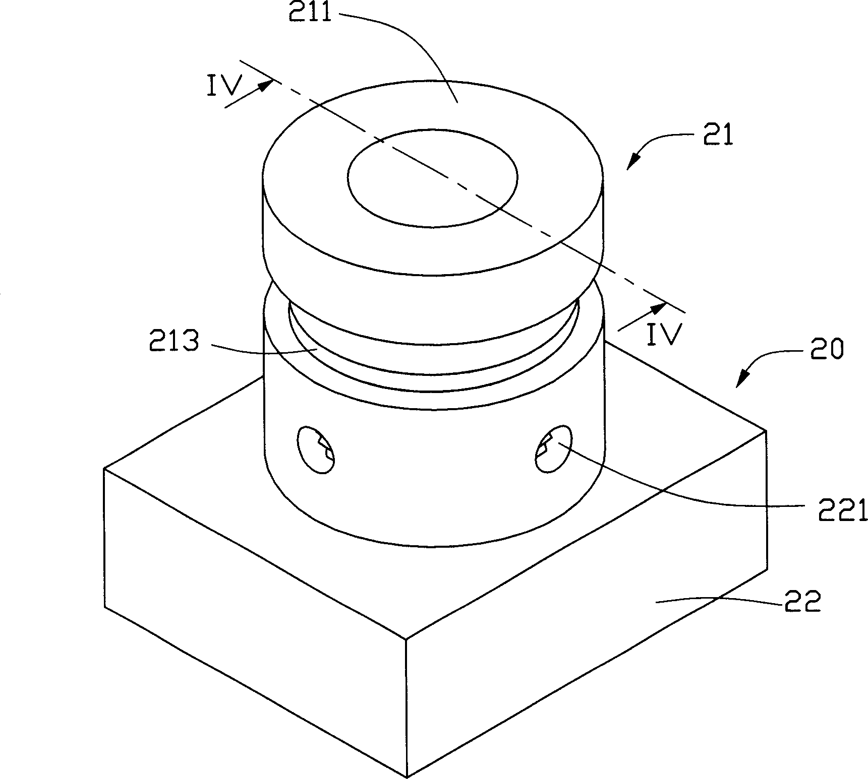
[0014] Please refer to image 3 , Figure 4 and Figure 5 , the lens module fixing structure 20 of the present invention includes a lens module 21 and a lens holder 22, wherein the lens module 21 is composed of a lens barrel 211 and a plurality of lenses 212, etc., and the lens holder 22 includes a peripheral wall (not marked). The outer wall of the barrel 211 and the inner wall of the lens holder 22 are respectively tapped with a certain length of thread (not marked), and there is an annular dispensing groove 213 on the outer wall of the lens barrel 211. The annular dispensing groove 213 is mainly used for the final heat curing treatment. Accommodate the heat-curing glue, so that the heat-curing glue can fully contact the lens barrel 211 and the lens holder 22, thereby achieving a better bonding effect. In addition, several holes 221 are provided on the peripheral wall where the lens holder 22 and the lens barrel 211 are joined. Usually 4, and symmetrically distributed on t...


PUM


Abstract

This invention relates to a lens pattern assembly fixing structure and a method. The fixing structure includes a lens cone and a lens base, in which, screw threads and a gluing slot are set at the outside wall of the lens cone, several holes are opened on the lens base circum wall and screw threads on the internal wall. The fixing method includes the following steps: putting the lens pattern assembly in the base then fixing the lens pattern assembly on the base with UV glue via several holes on the base circum wall, finally, heating the cure glue to fix it in the gluing slot at the joint of the base top and cone.

Description

【Technical field】 [0001] The invention relates to a lens module fixing structure and method applied to various cameras or optical instruments. 【Background technique】 [0002] At present, the fixed structure of the lens module used in cameras or optical instruments in the industry is mainly fixed with glue 10, please refer to figure 1 and figure 2 , the structure includes a lens module 11 and a lens holder 12, the lens module 11 is composed of a lens barrel 111 and a plurality of lenses 112, the outer wall of the lens barrel 111 and the inner wall of the lens holder 12 are threaded, and the lens module 11 is connected by threads, Then glue is dispensed and fixed at the joint between the lens barrel 111 of the lens module 11 and the upper end of the lens holder 12 . In this method, the lens module is screwed into the lens holder by threads first, and the optical effect is adjusted by the threads. When the optical effect is the best, then glue is dispensed at the joint betwe...

Claims


Application Information

Patent Timeline
IPC IPC(8): G02B7/02
Inventor 李俊佑蔡明江江宗韦
Owner HONG FU JIN PRECISION IND (SHENZHEN) CO LTD
Why Eureka
Try Eureka