
Multi- core optical connector assembly

A technology for optical connectors and components, applied in the directions of optical components, optics, light guides, etc., can solve the problems of inability to insert and ensure that multi-core ferrules are aligned with each other.

Inactive Publication Date: 2005-12-14
TYCO ELECTRONICS JAPAN GK
View PDF0 Cites 8 Cited by
  • Summary
  • Abstract
  • Description
  • Claims
  • Application Information

AI Technical Summary

Problems solved by technology

Therefore, even if the guide pins of the first housing are inserted into the guide holes of the second housing to align them with each other, the alignment of the multi-core ferrules with each other cannot be ensured.
In other words, it is still possible that the ferrule guide pin, which acts as the final guide, cannot be inserted into the guide hole of the ferrule, depending on the outer dimensions of the multi-core ferrule and the opening of the housing

Method used


Image

  • Multi- core optical connector assembly
  • Multi- core optical connector assembly
  • Multi- core optical connector assembly

Examples


Embodiment Construction

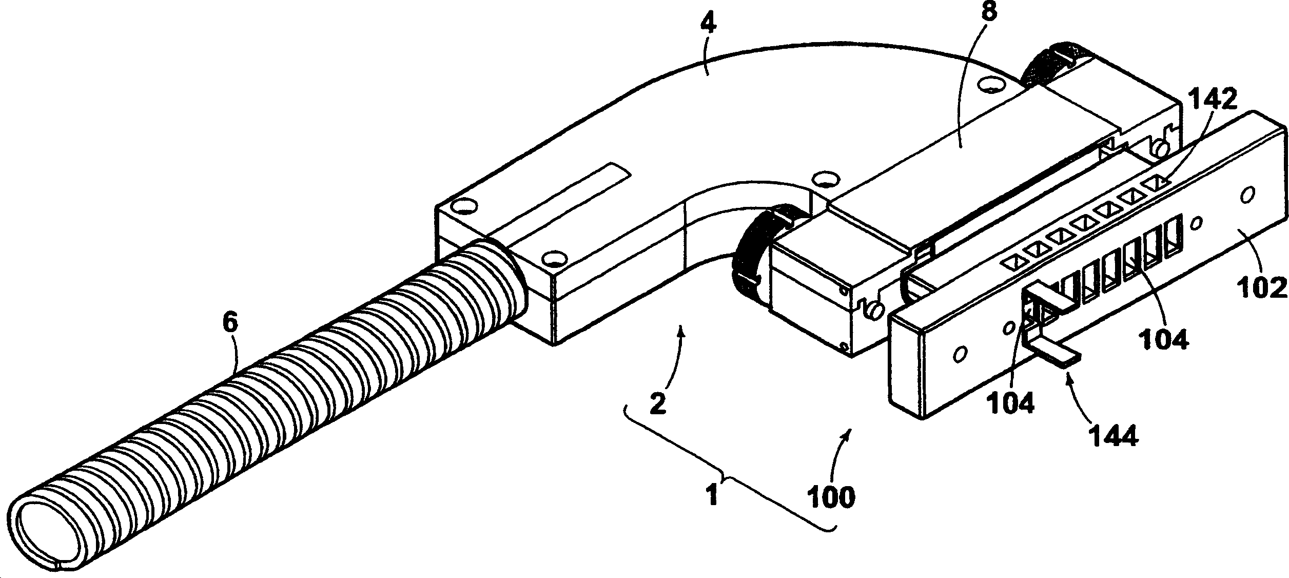
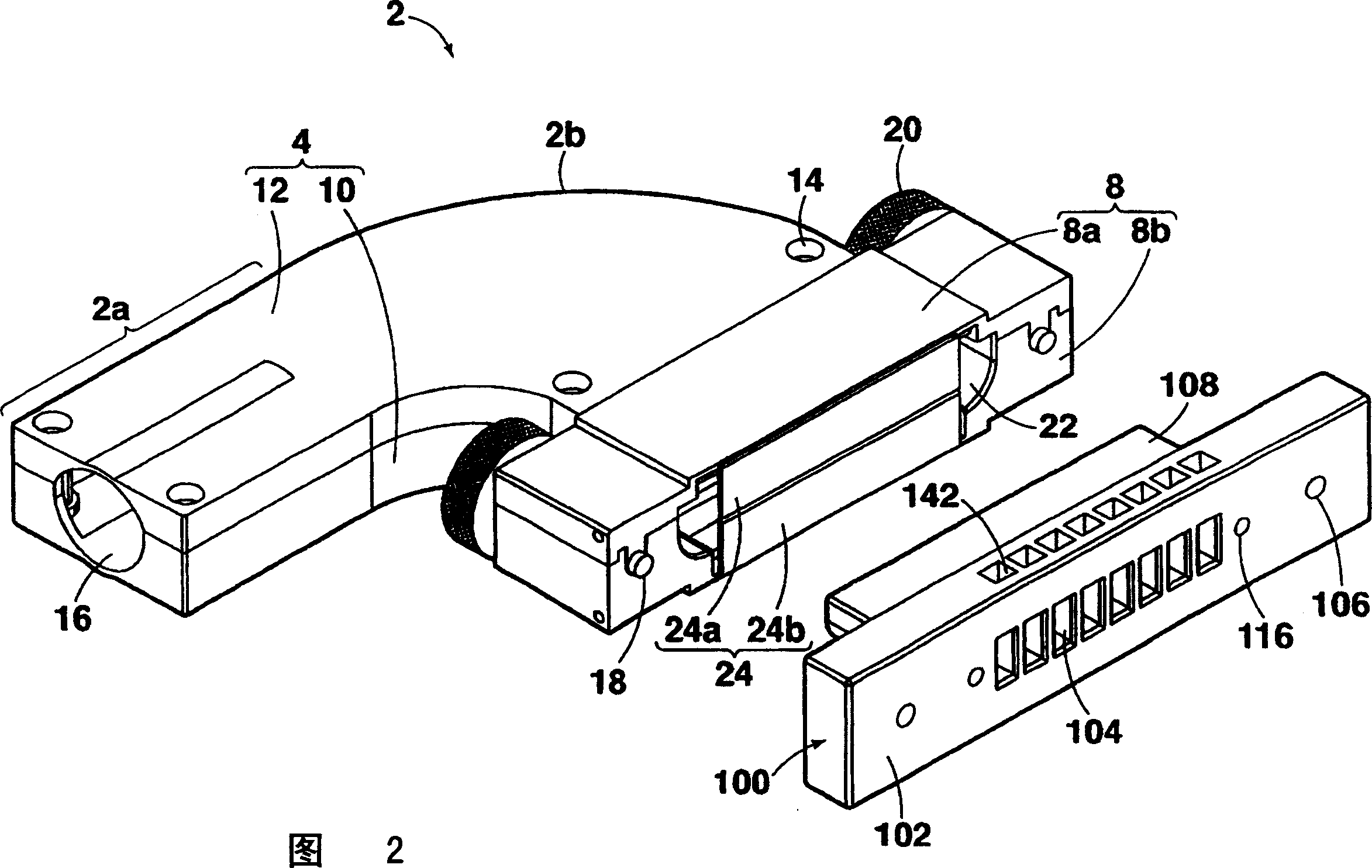
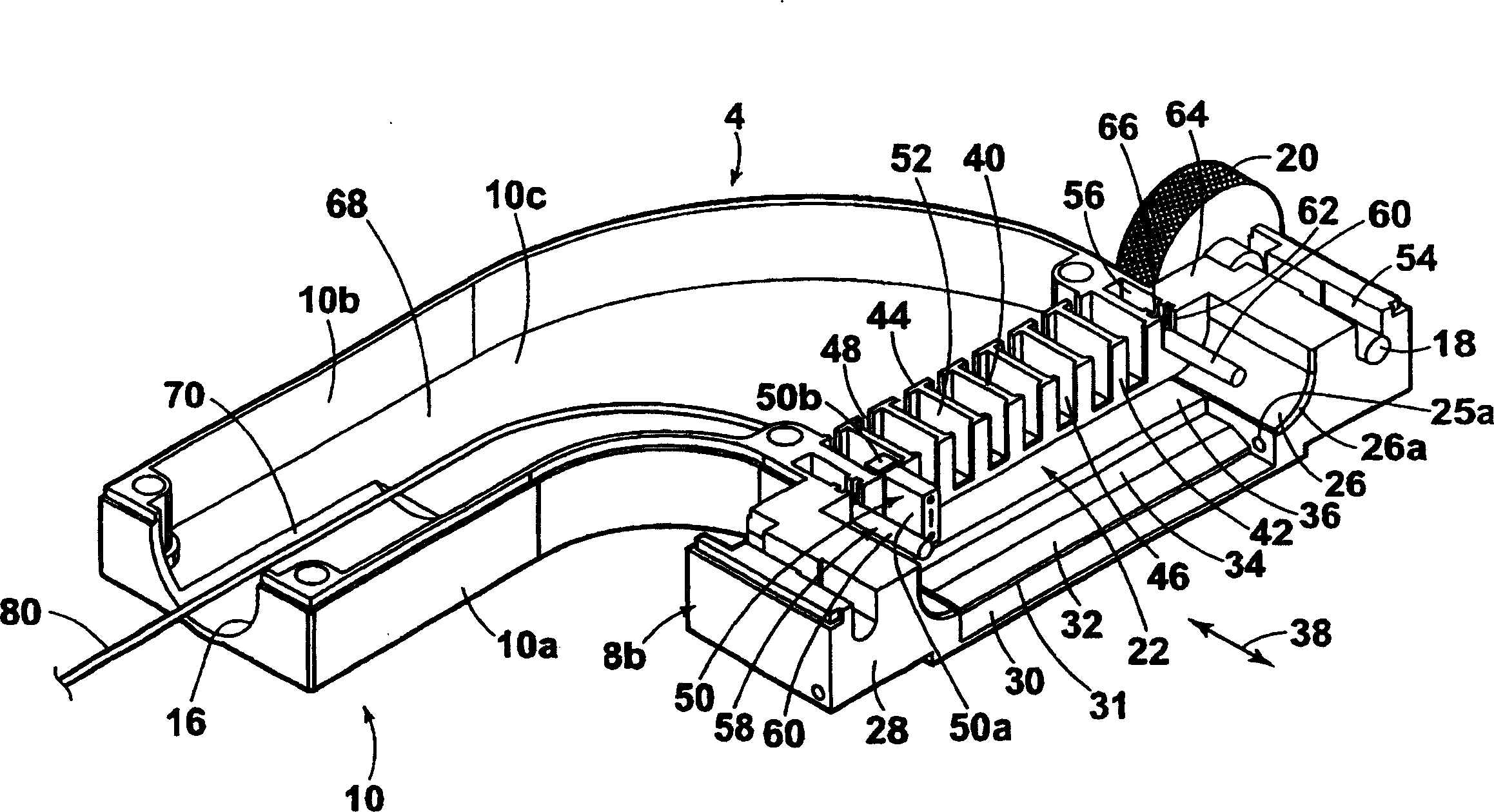
[0049] Embodiments of the multi-core optical connector assembly of the present invention will be described in detail below with reference to the accompanying drawings. figure 1 It is a perspective view showing the appearance of the multi-fiber optical connector module 1 (hereinafter simply referred to as "module") of the present invention. Such as figure 1 As shown, the assembly 1 is composed of a plug-side optical connector 2 and a receptacle-side optical connector 100 . The plug-side optical connector 2 has a housing 4 (plug housing) formed of die-cast aluminum or molded of conductive resin. A metal pipe 6 is connected to the casing 4 . Fiber optic cables are arranged in this tube 6 . Thus, the tube 6 needs to be flexible but still strong enough to prevent crushing. A rectangular joint portion 8 is formed on the housing 4 . The joint portion 8 is connected to the receptacle-side optical connector 100 .

[0050] Such as figure 1As shown, the receptacle-side optical con...


PUM


Abstract

The first guide means are formed by the inner configuration of the engagement portion of the plug housing and the outer configuration of the engagement portion of the socket housing to be guided and inserted into said engagement portion of the plug housing. The second guide mechanism is formed by a guide post and a guide post hole. The third guide mechanism is formed by the inner configuration of the engagement portion of the receptacle housing, and the outer configuration of the first multi-core ferrule of the plug-side optical connector to be inserted into the engagement portion of the receptacle housing. The fourth guide mechanism is formed by the guide pin of the second multi-core ferrule and the guide pin hole of the first multi-core ferrule for receiving the guide pin. During the mating process of the receptacle-side optical connector and the plug-side optical connector, the above-mentioned first, second, third, and fourth guide mechanisms work in this order.

Description

technical field [0001] The present invention relates to a multi-fiber optical connector assembly, and more particularly, to a multi-fiber optical connector assembly that connects a plurality of ferrules holding ends of optical fiber cables to each other. Background technique [0002] As a multi-fiber optical connector assembly, there is known a multi-fiber optical connector assembly disclosed in Japanese Unexamined Patent Application No. 2002-148486 ( figure 1 , Figure 4 ). This multi-core optical connector assembly includes: a plug-side optical connector composed of a first housing and a guide housing outside the first housing; a receptacle-side optical connector composed of a second housing. The first housing accommodates a plurality of multi-core ferrules with ferrule guide pins and also has guide pins. The second housing accommodates a plurality of multi-core ferrules with ferrule guide holes, and also has guide holes for receiving guide pins of the first housing. A...

Claims


Application Information

Patent Timeline
IPC IPC(8): G02B6/40G02B6/38
CPCG02B6/3829G02B6/3849G02B6/3879G02B6/3885G02B6/38
Inventor 大津信亮林武弘小林茂
Owner TYCO ELECTRONICS JAPAN GK
Learn More