
Connector device for card use

The technology of a card connector and a pushing device is applied to the parts of the connecting device, the device for preventing wrong connection, and the direction of connection, which can solve the problem of scratching the card, prevent the card from flying out, and increase the frictional force. , the effect of reducing the number of parts

Inactive Publication Date: 2005-12-14
ALPS ALPINE CO LTD
View PDF1 Cites 4 Cited by
  • Summary
  • Abstract
  • Description
  • Claims
  • Application Information

AI Technical Summary

Problems solved by technology

[0014] However, in the structure of the existing card connector device, when the card is ejected, the card is pressed downward by the guide fittings, so the card will not suddenly fly out of the box, but the problem is that the The restraining part in contact with the card is a metal sheet, which will scratch the card

Method used


Image

  • Connector device for card use
  • Connector device for card use
  • Connector device for card use

Examples


Embodiment Construction

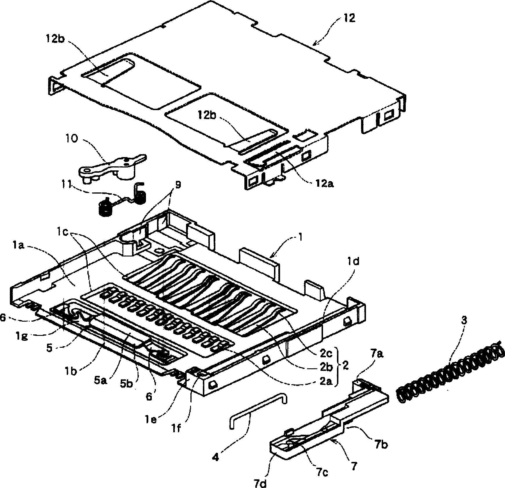
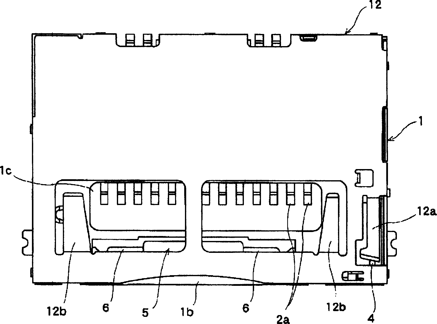
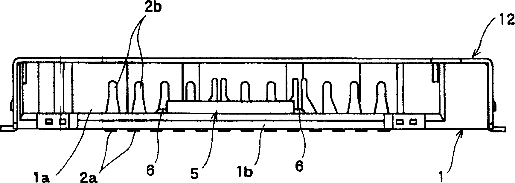
[0041] under, Figure 1 to Figure 8 Embodiments of the present invention are shown. figure 1 is an exploded perspective view of the card connector unit, figure 2 is a plan view showing the card connector device, image 3 is a front view showing the card connector device, Figure 4 It is a top view of the card connector device showing a state where the cover is removed, Figure 5 is a sectional view of the main part showing the pressing device when the card is not inserted, Image 6 is a sectional view of the main part showing the pressing device when the card is not inserted, Figure 7 is a sectional view of the main part showing the pressing device when the card is inserted, Figure 8 It is a sectional view of main parts showing the pressing device when the card is inserted.

[0042] In the figure, the casing 1 is formed of an insulating material such as synthetic resin into a square box shape with front and upper openings. A housing portion 1a is provided at the cen...


PUM


Abstract

PROBLEM TO BE SOLVED: To provide a connector device for cards which prevents cards from flying out, when the cards are ejected, and causes no damage to the cards. ŽSOLUTION: The connector device for cards is provided with a housing 1 having an accommodation part 1a on which a card is mounted, a connector terminal 2 which is arranged at one end of the accommodation part 1a and attachable to the card 13, a slide member 7 which can move in the directions in which the card 13 is inserted and ejected, an energizing member 3 which energizes the slide member 7, a heart-shaped groove 7c which holds the slide member 7 at a card-mounting position, and a lock member 4. The accommodation part 1a of the housing 1 is provided with a pressing means which presses the card 13 in its thickness direction when the slide member 7 is moved to a card-ejecting position by the energizing member 3. The pressing means comprises a plastic card contact section 5 and a metallic spring chip 6 which presses the card contact section 5 to the card 13. ŽCOPYRIGHT: (C)2006,JPO&NCIPI Ž

Description

technical field [0001] The present invention relates to a structure of a card connector device used for a compact memory card used in various portable information terminals such as mobile phones and PCs, digital cameras, digital AV equipment and other memory-compatible devices. Background technique [0002] As a card loaded with an IC, a memory, and the like, an IC card, a memory card, and the like are widely used. Card connector devices are used to electrically connect such IC cards, memory cards, and the like to a circuit board on the device side. [0003] The existing card connector device is equipped with a card ejection mechanism in the case where the card can be inserted and pulled out. In this card ejection mechanism, a push-push structure has been developed, which pushes the card into the connector. Insert it, and when it is discharged, it is pushed out again. At this time, due to the ejection operation of the card, the slider moves suddenly in the box, so that the...

Claims


Application Information

Patent Timeline
IPC IPC(8): G06K17/00H01R13/629H01R13/64
Inventor 横田纯一郎黑田嘉成
Owner ALPS ALPINE CO LTD
Learn More