

Cab of construction machinery
A technology for construction machinery and driver's cab, applied in the direction of earth mover/shovel, motor vehicle, construction, etc., can solve problems such as damage of driver's cab, and achieve the effect of reducing weight, ensuring strength, and sufficient strength
- Summary
- Abstract
- Description
- Claims
- Application Information
AI Technical Summary
Problems solved by technology
Method used
Image

Examples
Embodiment Construction
[0047] Hereinafter, embodiments of the present invention will be described with reference to the drawings, taking a case where a construction machine cab is applied to a hydraulic excavator as an example.
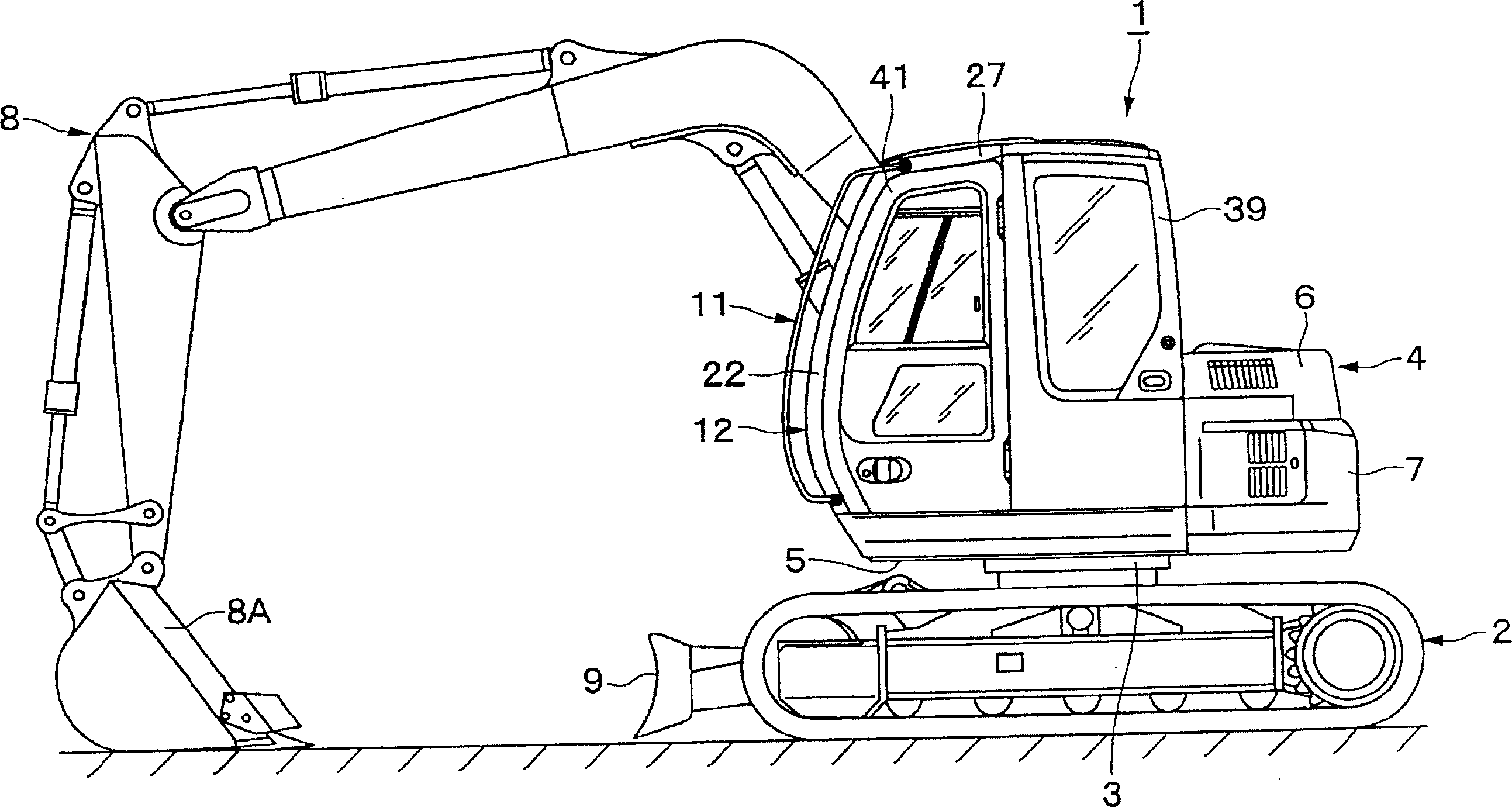
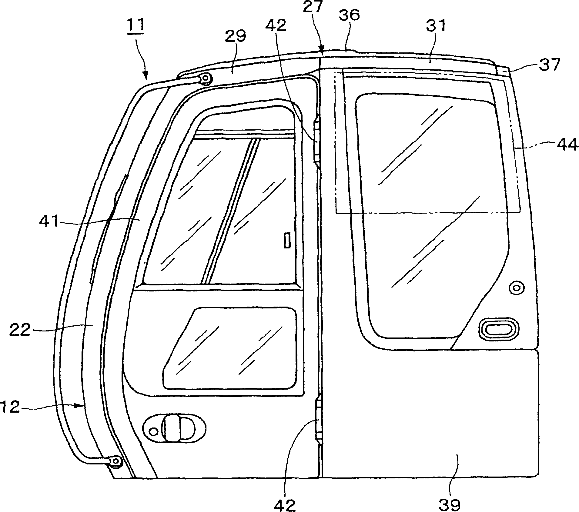
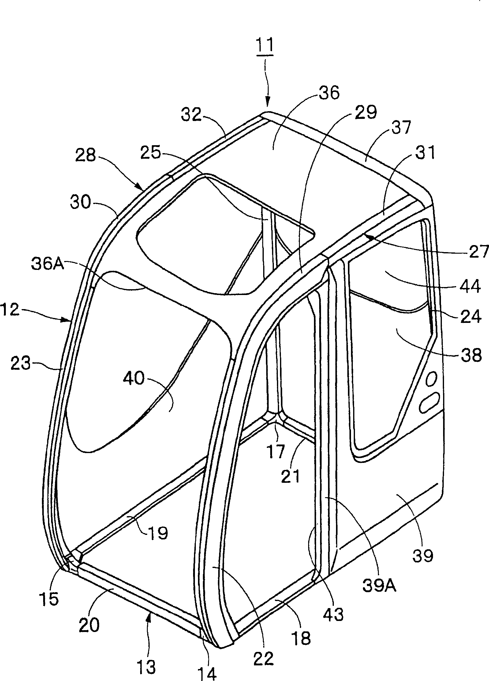
[0048] here, Figure 1 to Figure 10 It is the first embodiment of the present invention. In the figure, 1 is a hydraulic excavator as a construction machine. This hydraulic excavator 1 is roughly composed of a lower traveling body 2, an upper rotating body 4 rotatably mounted on the lower traveling body using rotating wheels 3, and a working device described later. 8 composition.
[0049] In addition, the upper slewing body 4 is generally provided on the revolving frame by the revolving frame 5, the driver's cab 11 described later mounted on the front left side of the revolving frame 5 when viewed from the rear of the vehicle, and the rear side of the driver's cab 11. The exterior cover body 6 on 5, the counterweight 7 that is installed on the rear end portion of rotating...
PUM
 Abstract
Description
Claims
Application Information