Time delay estimation method and system for use in ultrasound imaging

一种时间延迟、超声系统的技术,应用在使用声波/超声波/次声波进行材料分析、无线电波测量系统、超声波/声波/次声波诊断等方向,能够解决错误波束形成器转向等问题

Inactive Publication Date: 2006-01-04
GENERAL ELECTRIC CO
View PDF0 Cites 22 Cited by
  • Summary
  • Abstract
  • Description
  • Claims
  • Application Information

AI Technical Summary

Problems solved by technology

If such a signal is used to estimate the time delay error, the correction to the observed time of arrival error would incorrectly steer the beamformer toward the scatterer

Method used


Image

  • Time delay estimation method and system for use in ultrasound imaging
  • Time delay estimation method and system for use in ultrasound imaging
  • Time delay estimation method and system for use in ultrasound imaging

Examples


Embodiment Construction

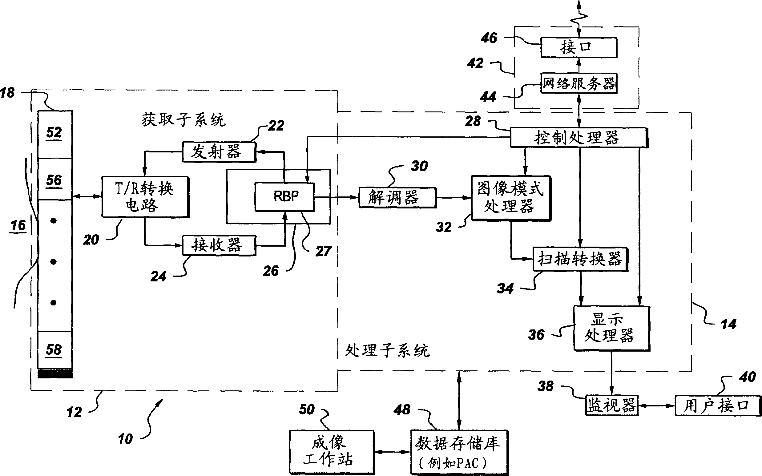
[0027] figure 1is a block diagram of one embodiment of an ultrasound system 10 implemented in accordance with an aspect of the present invention. The ultrasound system includes an acquisition subsystem 12 and a processing subsystem 14 . Acquisition subsystem 12 includes transducer array 18 (including a plurality of transducer array elements), transmit / receive conversion circuitry 20 , transmitter 22 , receiver 24 and beamformer 26 . The beamformer 26 includes a receive beamformer processor (RBP) 27 . Processing subsystem 14 includes control processor 28 , demodulator 30 , imaging mode processor 32 , scan converter 34 and display processor 36 . The display processor is also connected to a monitor for displaying images. A user interface 40 interacts with the control processor and the display monitor. The processing subsystem is also connectable to a remote connectivity subsystem 42 which includes a web server 44 and a remote connectivity interface 46 . The processing subsys...


PUM


Abstract

The present invention provides a method that is used for correcting the time delay between at least two signals of an ultrasonic system. The ultrasonic system (10) comprises wave-stream formation processor (27) with an adder (64) and a complex filter (66). The adder is connected with an energy-exchanging device array (18) and is configured to be used for performing the complex operation for a first multiple receiving signal so as to generate the wave stream and the signal; wherein, each of the receiving signals contains a delay that is formed by the corresponding wave stream, and the complex filter (66) is connected with the adder, which is configured to be used for transforming the wave stream and the signal into an analysis signal. The wave-stream formation processor also comprises a plurality of correlation-device processors (68) that are connected with at least one corresponding energy-exchanging device unit and the complex filter and at least one time delay estimation device that is applied to receiving at least one correlation sum of the receiving signal and is configured to be used for estimating the corresponding time delay according to the correlation sum; and every correlation-device processor is configured to be used for calculating the correlation sum of at least one receiving signal.

Description

technical field [0001] The present invention relates generally to imaging systems, and more particularly to methods and systems for estimating and correcting time delays in ultrasound imaging systems. Background technique [0002] An ultrasound system includes an array of transducer elements for transmitting a set of waveforms into an imaged subject and for receiving a set of reflected ultrasound signals. Each waveform is transmitted with a relative time delay selected to focus the set of transmitted waveforms in a desired direction and depth and in a desired shape. Similarly, each received signal is individually delayed to maximize the system's response to reflected energy in a desired direction and depth and having a desired shape. The delayed received signals are summed and processed to generate and display an image of the imaged subject. [0003] Transmit and receive time delays, collectively referred to as beamforming time delays, are typically calculated assuming sou...

Claims


Application Information

Patent Timeline
Patent Type & Authority Applications(China)
IPC IPC(8): A61B8/00G01N29/00
CPCG01S7/5205G10K11/346G01S7/52025A61B8/00
Inventor K·W·里格比S·C·米勒
Owner GENERAL ELECTRIC CO
Why Eureka
Try Eureka