Work piece transport system

A technology for conveying systems and workpieces, which is applied to the field of workpiece conveying systems for conveying in the workpiece storage unit, which can solve problems such as operating restrictions, increased product costs, and time-consuming recovery, and achieves reduced product costs, high speed, and simple separate supply Effect

Active Publication Date: 2006-01-04
TOKYO WELD CO LTD
View PDF1 Cites 3 Cited by
  • Summary
  • Abstract
  • Description
  • Claims
  • Application Information

AI Technical Summary

Problems solved by technology

[0008] In this kind of workpiece conveying system, along with the miniaturization of parts, the separation pin 25a is also extremely thin and easy to break, and it is difficult to install the separation pin 25a and the drive mechanism 25b, and the continuity of the movement of the separation pin 25a such as going out and in is not guaranteed. The operation of the device is restricted, and as a result, it becomes one of the reasons for restricting the speed-up
[0009] In addition, because the covers 28b and 24 are generally provided on the conveying path 28a and the communication path 29a, it is easy to cause workpiece clogging.
Once a workpiece clogging phenomenon occurs, it takes time to recover, or a recovery mechanism called a recovery device is installed, because the clogged workpiece W must be removed. 10 , so there is a problem of rising product cost

Method used


Image

  • Work piece transport system
  • Work piece transport system
  • Work piece transport system

Examples


Embodiment Construction

[0032] Hereinafter, embodiments of the present invention will be described with reference to the drawings.

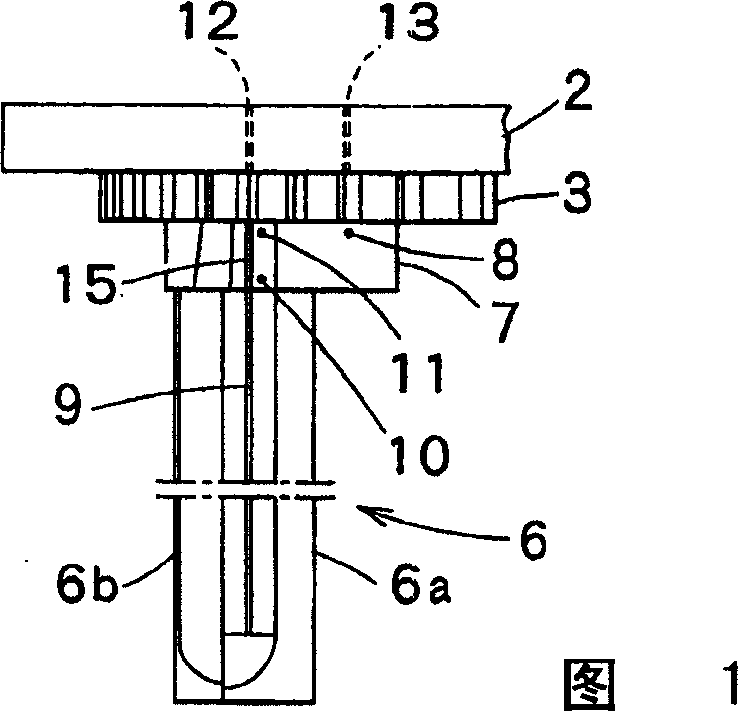
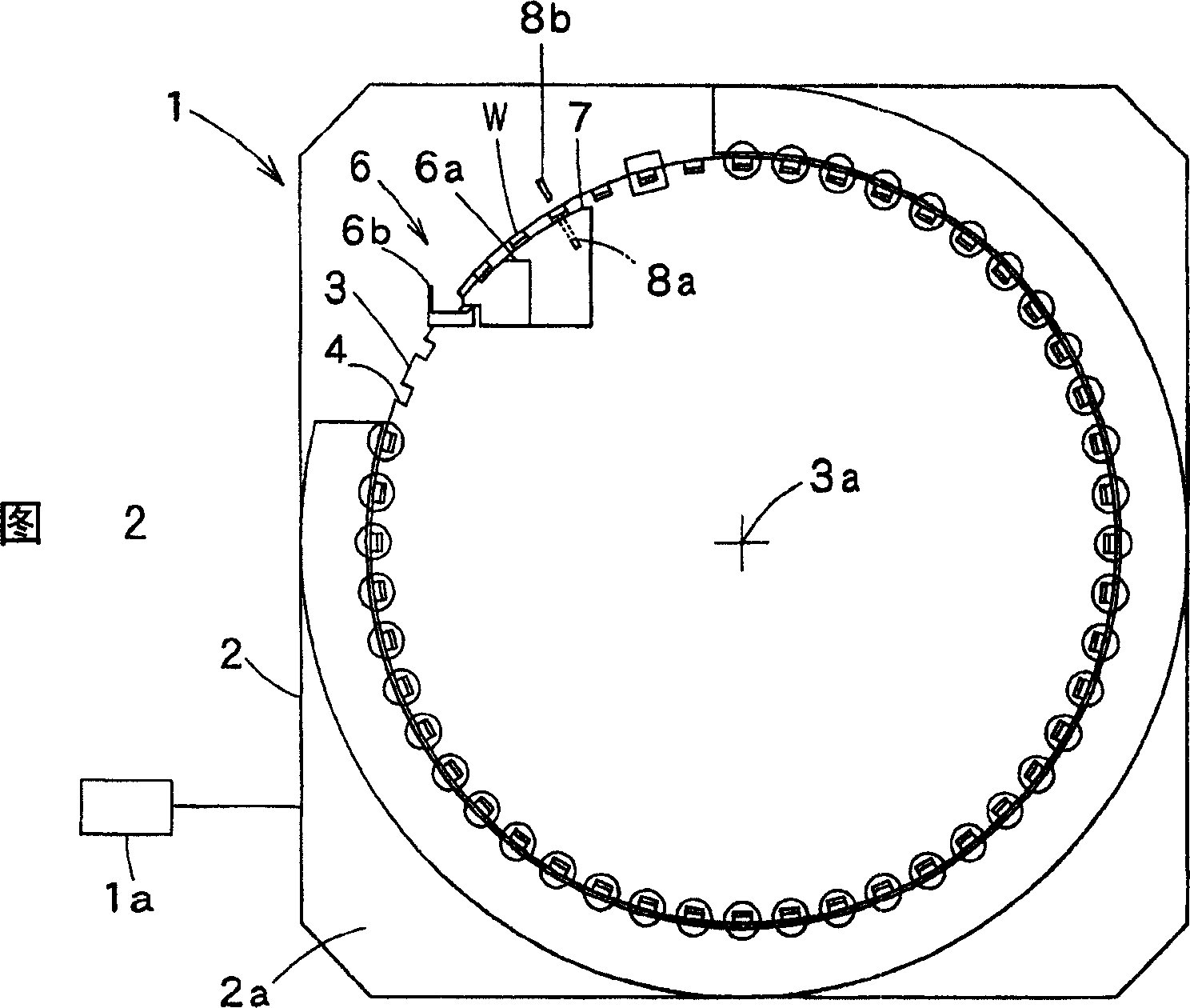
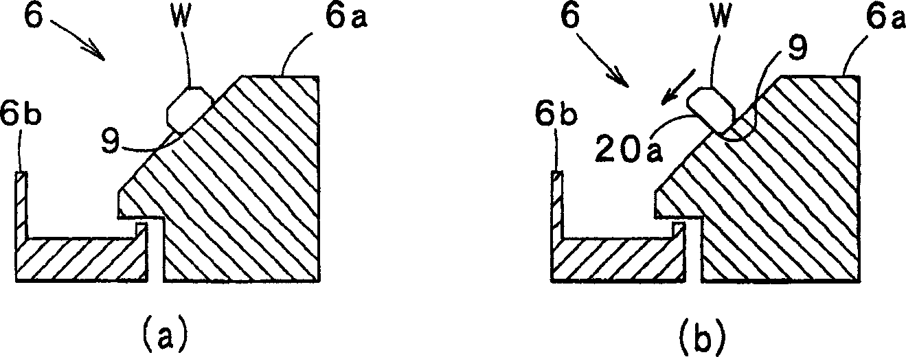
[0033] FIG. 1 is a plan view showing an embodiment of the workpiece conveying system of the present invention, and FIG. 2 is a front view showing the workpiece conveying system, image 3 (a) is an enlarged cross-sectional view of a linear feeder in a normal conveying state, image 3 (b) is an enlarged cross-sectional view of the linear feeder in an abnormal conveying state, and Fig. 4(a) to Fig. 4(c) are explanatory views of the supply feeder, Figure 5 6 is a front view showing the separation chute, FIG. 6 is a side view showing the workpiece loading hole, and FIG. 7 is a side view showing the workpiece discharge hole.

[0034] In Fig. 1 and Fig. 2, the workpiece conveying system 1 includes: a vertically arranged workbench base 2; arranged on the vertical surface 2a of the workbench base 2, arranged around the horizontal rotation axis 3a to rotate freely intermittently,...


PUM


Abstract

To provide a work conveying system capable of reliably charging works one by one in a work storage part of a conveying table without stuffing of the works. The work conveying system comprises a vertically arranged table base 2, a conveying table 3 which is rotatably arranged on the table base 2, and a linear feeder 6 arranged orthogonal to the conveying table 3. A separation chute 7 to separate works w fed from the linear feeder 6 one by one is provided between the linear feeder 6 and the conveying table 3. Each work w has a rectangular section, and a feeder 6a of the linear feeder 6 has a first V-shaped groove 9 having a long side 9a and a short side 9b. When a long side 20a of the work w reaches the short side 9b of the first V-shaped groove 9, the work w is dropped from the feeder 6a.

Description

technical field [0001] The present invention relates to a workpiece conveying system that loads and conveys workpieces one by one into a workpiece storage portion of a conveying table, and more particularly relates to a system that separates workpieces conveyed in contact with each other one by one and supplies them to the workpiece storing portion of a conveying table Workpiece conveyor system. Background technique [0002] A workpiece conveyance system shown in FIG. 9 has been known for a long time (refer to Patent Document 1). In FIG. 9 , the workpiece conveying system has a workpiece feeder 28 and a separation mechanism 29 . Among them, the workpiece feeder 28 is formed by forming the workpiece W 10 The supporting table 28a of the conveying path, and the preventing workpiece W covering the conveying path 10 The cover 28b for scattering is constituted, and the workpiece W 10 Connected and lined up for delivery. [0003] The separation mechanism 29 connected to the do...

Claims


Application Information

Patent Timeline
Patent Type & Authority Applications(China)
IPC IPC(8): B65G29/00B65G47/26
CPCB23P19/005B23Q7/02B23Q7/08B23Q7/12B23Q17/2447B23Q2707/04B65G47/14
Inventor 小岛智幸吉泽诚二水野显治小平晃久
Owner TOKYO WELD CO LTD
Why Eureka
Try Eureka