Rolling ball tribometer

A support ball, ball contact technology, applied in the field of rotating ball tribometer, can solve the problem of expensive, time-consuming, non-practical parts, etc.

Inactive Publication Date: 2006-01-04
AIR PROD & CHEM INC
View PDF5 Cites 2 Cited by
  • Summary
  • Abstract
  • Description
  • Claims
  • Application Information

AI Technical Summary

Problems solved by technology

However, both fatigue testing and rolling contact wear testing are extremely time-consuming, expensive, and require specialized testing equipment
Also, component testing is usually limited to standard samples rather than actual components
Pin and dial testing is rarely used for functional critical components and most are limited to teaching and qualitative measurements

Method used


Image

  • Rolling ball tribometer
  • Rolling ball tribometer
  • Rolling ball tribometer

Examples


Embodiment Construction

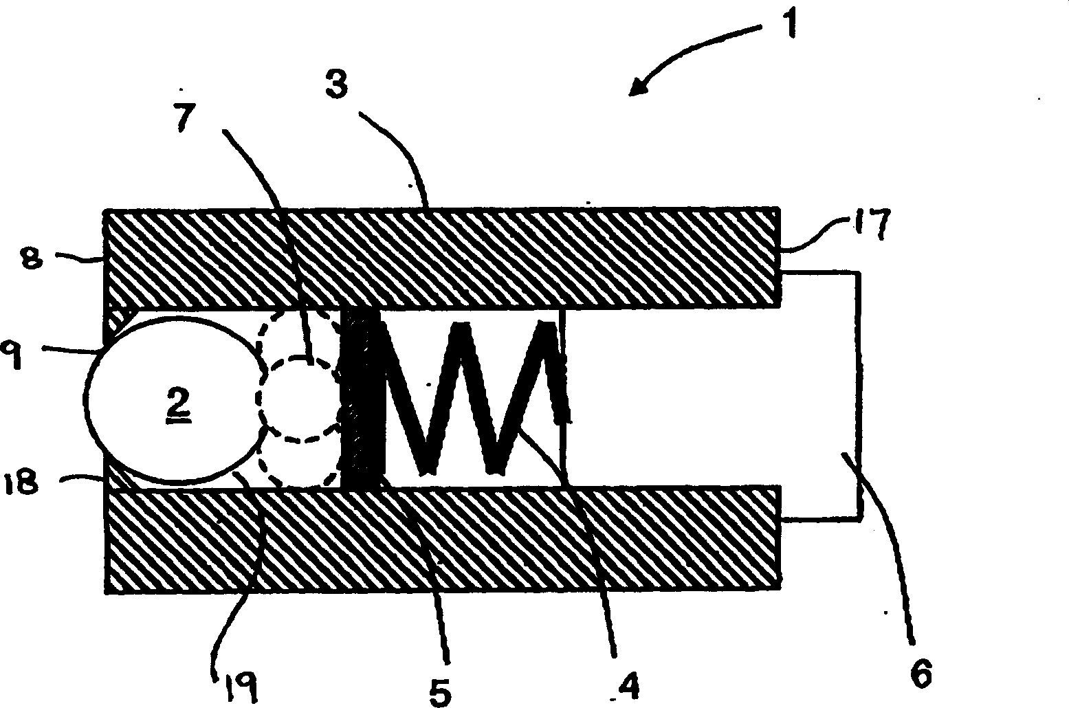
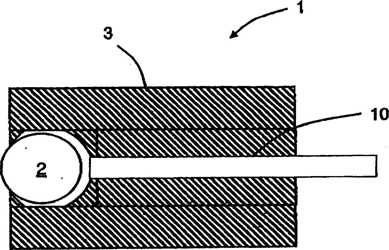
[0018] The invention relates to a friction device comprising a ball, a support, and means for exerting a substantially constant force on the ball against the part. Additionally, the present invention provides a method of influencing wear and / or fatigue of components for friction analysis. Although parts that have not been machined can be tested using the devices and methods of these inventions, these inventions are particularly useful for measuring parts that have been machined.

[0019] In order to facilitate the understanding of friction devices suitable for influencing wear and / or fatigue of components, reference is made to the accompanying drawings. (The same numerals are used in the figures to denote like elements in different embodiments of the devices shown.) Any component can be tested using the devices and methods of the present invention, including components that would withstand abrasion or sticking in normal (future) use. Connect worn parts. The parts to be teste...


PUM

PropertyMeasurementUnit
diameteraaaaaaaaaa
diameteraaaaaaaaaa
lengthaaaaaaaaaa

Abstract

This invention is directed to a tribological apparatus and method incorporating a ball, a support, and means for maintaining a substantially constant force between the ball and a test surface. The ball rolls against the rotating test surface producing a wear track. Analysis relating to wear and fatigue can be performed on the test surface subsequent to producing the wear track.

Description

technical field [0001] Functionally critical components like bearings, bearing races, valves, medical implants, gears, etc. are subject to abrasive or adhesive wear in service. In demanding applications, the performance of such components is directly related to the quality of the machined surface, including its surface finish, surface and subsurface hardness, and residual stress profile. However, the wear performance and fatigue life of components also depend on the working material composition, the microstructure of the original material and the heat treatment process, and likewise, pre-simulation of fatigue life is often full of inaccurate and oversimplified assumptions. Conducted actual wear or fatigue life testing is often the only true measure of component performance. [0002] Fatigue testing involves applying a specific device load (possibly zero) as well as alternating loads (axial, torsional, or flex) to the component under test and then recording the number of revol...

Claims


Application Information

Patent Timeline
Patent Type & Authority Applications(China)
IPC IPC(8): G01N19/00G01N3/56G01M13/00
Inventor Z・祖雷基R・格霍斯L・M・格里姆
Owner AIR PROD & CHEM INC
Why Eureka
Try Eureka