Rolling ball tribometer

a tribometer and rolling ball technology, applied in the direction of rolling contact bearings, rotary bearings, shafts and bearings, etc., can solve the problems of high cost, high labor intensity, and inability to accurately predict the life of fatigue tests and rolling contact wear tests, etc., to shorten the evaluation time of parts, simple, and inexpensive

Inactive Publication Date: 2005-12-15
AIR PROD & CHEM INC
View PDF11 Cites 5 Cited by
  • Summary
  • Abstract
  • Description
  • Claims
  • Application Information

AI Technical Summary

Benefits of technology

[0011] The part is preferably moved rotationally or linearly back-and-forth relative to the ball. The current inventions may provide a simple, inexpensive way for measuring and comparing the wear behavior of machined and unmachined surfaces, and may shorten the evaluation time for a part (from several hours or days to less than 1 hour).
[0012] The current inventions may provide flexibility to test actual parts, (and not specially prepared parts of a particular geometry), including cylindrical and other non-flat surfaces, making it possible to test actual parts for quality control or for process and material optimization. The current inventions may be used to test parts for wear or fatigue with or without lubricant or fluid under or around the rolling ball, or to test parts in a corrosive fluid, such as salt water, or with corrosive fluid under or around the rolling ball.

Problems solved by technology

However, the wear behavior and fatigue life of a part is also dependant on the work material composition, microstructure and heat treatment process of the starting material, and as such, predictive modeling of fatigue life is often fraught with inaccuracies and simplistic assumptions.
However, both fatigue tests and rolling contact wear tests are extremely time consuming, expensive and require dedicated test equipment.
In addition, part testing is usually limited to standard samples, and not actual parts.
The pin-on-disc test is rarely used for functionally critical parts and is mostly limited to academic and qualitative measurements.

Method used


Image

  • Rolling ball tribometer
  • Rolling ball tribometer
  • Rolling ball tribometer

Examples


example

Tribological Analysis of Various Machined Parts

[0036] The apparatus of the current invention was constructed and used to compare the wear of parts prepared by various machining conditions.

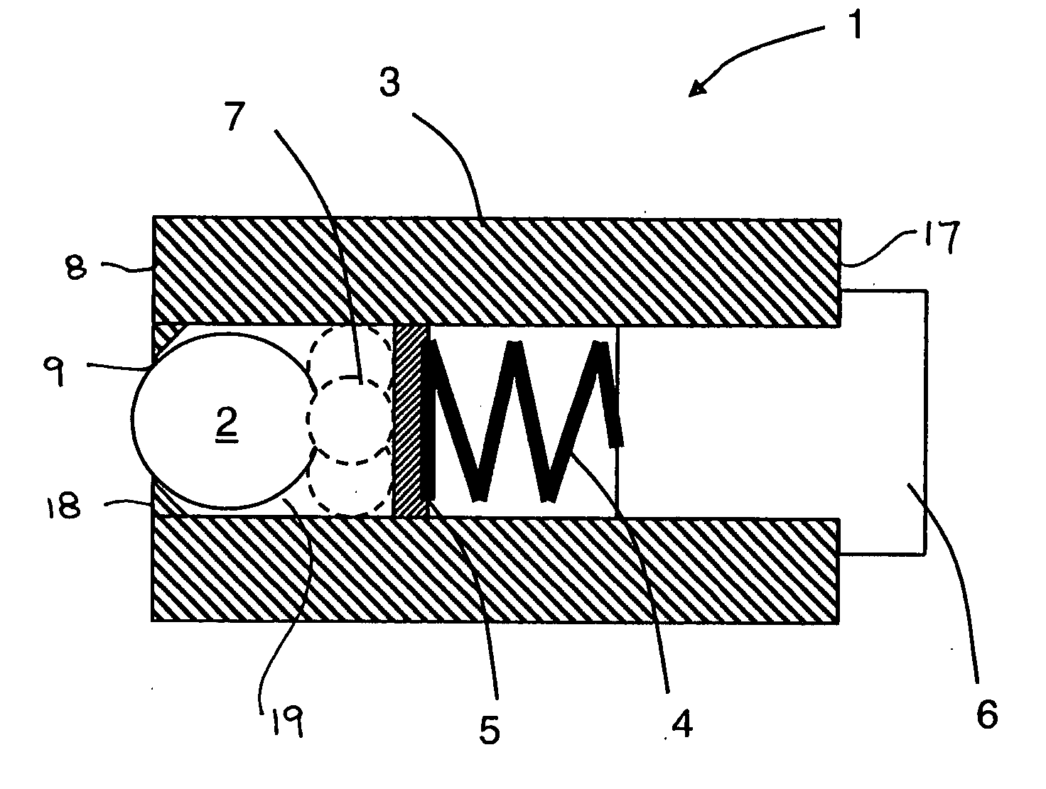
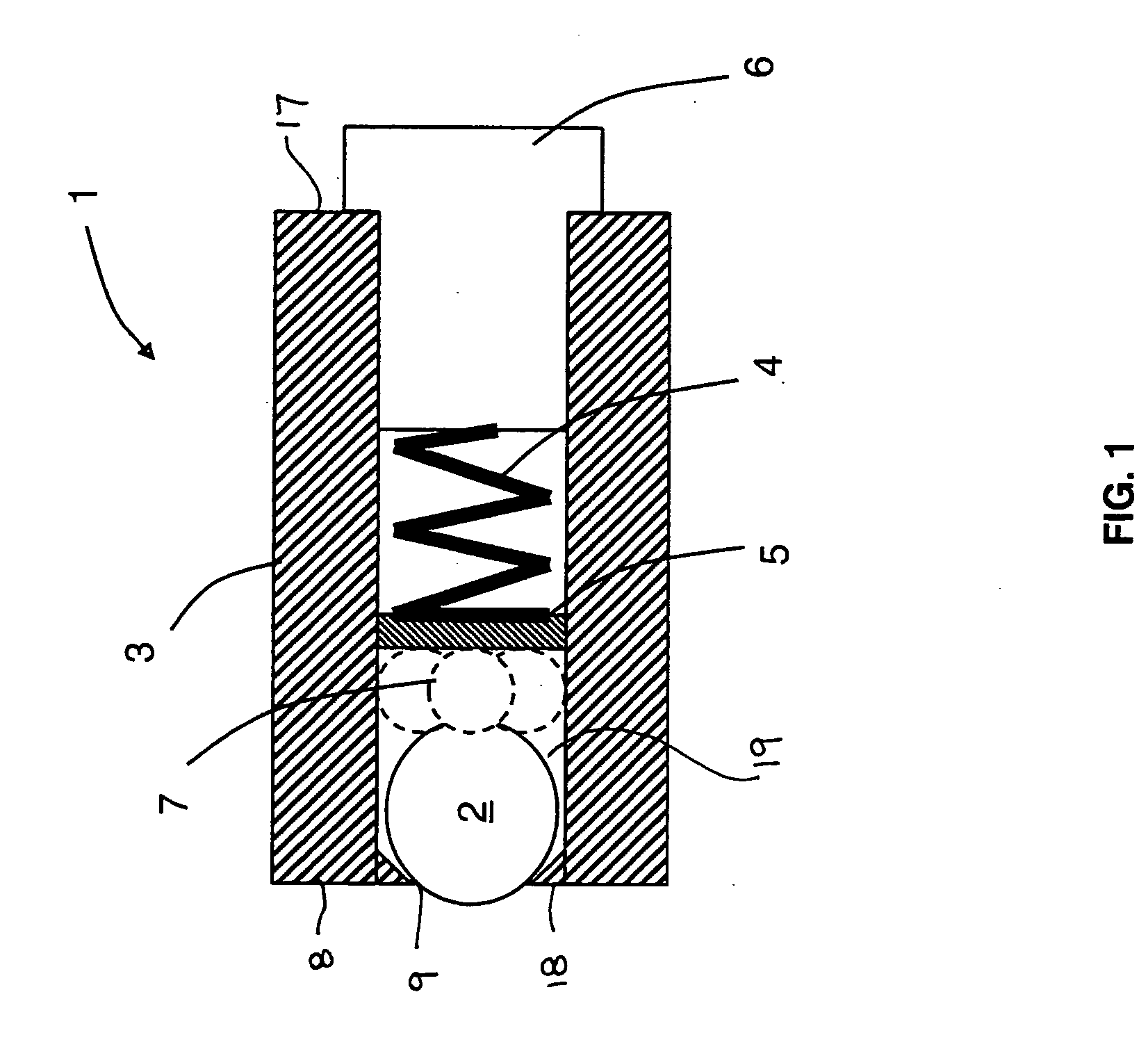
[0037] The support of the tribological device was constructed of carbon steel and machined to accommodate a rigid, inert, spherical ball. The rigid, inert, spherical ball was a sapphire ball with a diameter of 0.250 inch. Three ultrafine-grained alumina supporting balls with a diameter of 0.125 inch aligned the sapphire ball in the support. The diameter of the hole in the support that accommodated the balls was 0.270 inch, thereby providing a loose fit. The force to the sapphire ball was created by a compression spring. The compression spring had a free length of 0.440 inch, a spring rate of 174.9 lb / in (30.63 N / mm), and a load of 16.17 lb (71.92 N) at a length of 0.348 inch. A ceramic back plate was used between the compression spring and the ceramic supporting balls.

[0038] Three test parts wer...


PUM

PropertyMeasurementUnit
normal forceaaaaaaaaaa
contact surface speedaaaaaaaaaa

Abstract

This invention is directed to a tribological apparatus and method incorporating a ball, a support, and means for maintaining a substantially constant force between the ball and a test surface. The ball rolls against the rotating test surface producing a wear track. Analysis relating to wear and fatigue can be performed on the test surface subsequent to producing the wear track.

Description

BACKGROUND OF THE INVENTION [0001] Functionally critical parts like bearings, bearing races, valves, medical implants, gears, etc. undergo abrasive or adhesive wear in service. The performance of such a part in a demanding application is directly related to the quality of the machined surface, including its surface finish, surface and subsurface hardness and residual stress pattern. However, the wear behavior and fatigue life of a part is also dependant on the work material composition, microstructure and heat treatment process of the starting material, and as such, predictive modeling of fatigue life is often fraught with inaccuracies and simplistic assumptions. Conducting actual wear or fatigue life tests are often the only true gauge of part performance. [0002] Fatigue tests involve application of a specified mean load (which may be zero), as well as an alternating load (axial, torsional or flexural) to the part to be tested and then the number of cycles required to produce failu...

Claims


Application Information

Patent Timeline
Patent Type & Authority Applications(United States)
IPC IPC(8): G01N3/56
CPCG01N3/56
Inventor ZURECKI, ZBIGNIEWGHOSH, RANAJITGRIMM, LANCE MICHAEL
Owner AIR PROD & CHEM INC
Why Eureka
Try Eureka